


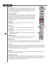
8
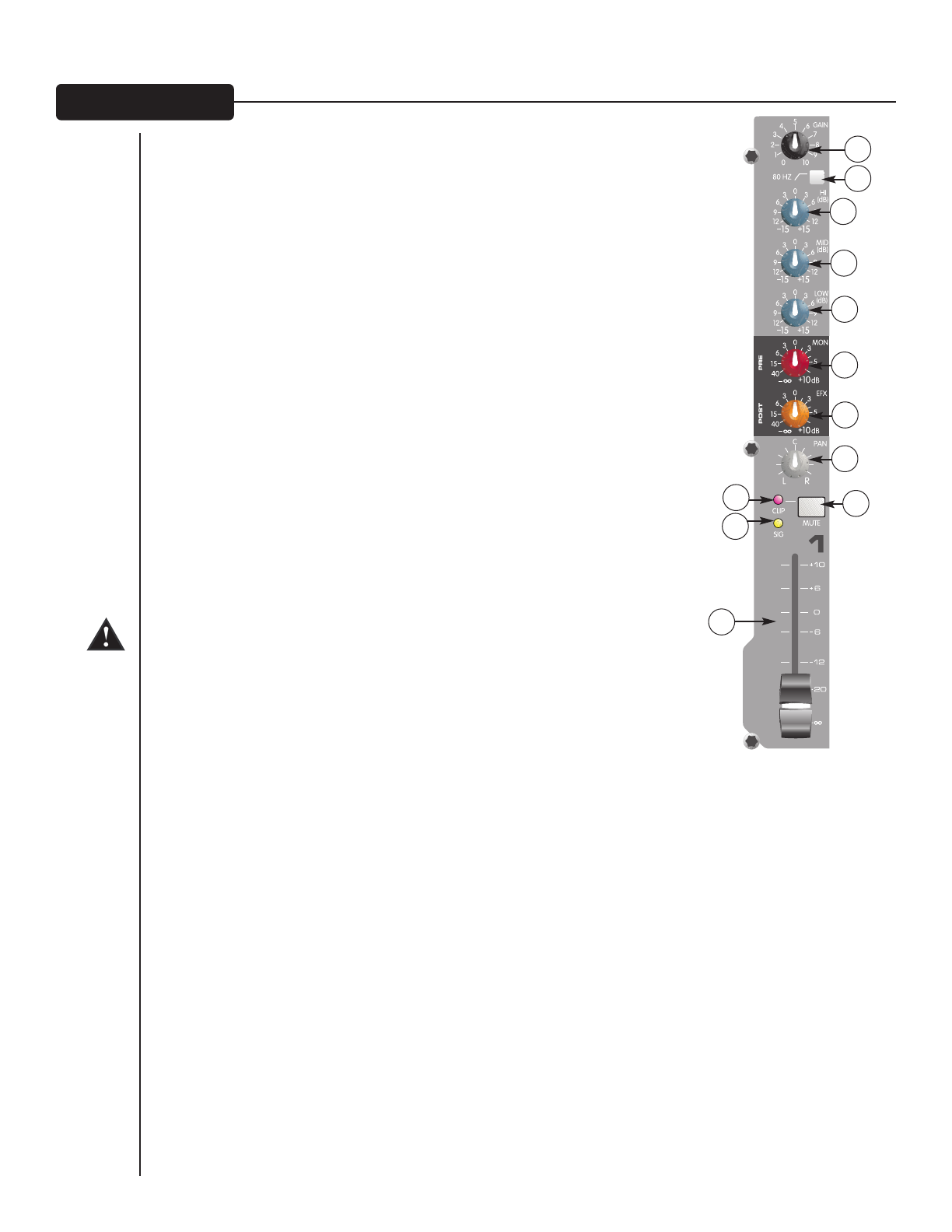
Gain (1)
This control establishes the nominal operating level for the channel. The input gain
can be adjusted over a wide range to compensate for soft voices or very loud
drums. To maximize the signal-to-noise ratio, the gain should be set to the proper
level, with the channel level control (12) set to 0. If the clip LED comes on and
remains lit, try reducing the gain.
80 Hz Low Cut (2)
The low cut filter has a corner frequency of 80 Hz. When engaged‚ it can improve
clarity by removing low frequencies that make a mix sound muddy. This feature is
especially useful when playing outside on a windy day or on a hollow-sounding‚
noisy stage. These kinds of ambient noises can rob your sound system of power.
Engaging this switch will remove those frequencies from the system and restore
power where needed.
Hi EQ (3)
An active tone control (shelving type: ±15 dB) that varies the level of the high
frequency range.
Mid EQ (4)
An active tone control (peak dip: ±15 dB) that varies the mid frequency range.
Low EQ (5)
An active tone control (shelving type: ±15 dB) that varies the level of the low
frequency range.
Caution: Excessive low frequency boost causes greater power consumption and increases the
possibility of speaker damage.
MON Send (6)
This control adjusts the level of the channel signal sent to the monitor output. The
signal is taken before the channel level control but after the channel EQ.
EFX Send (7)
This control adjusts the level of the channel signal added to the effects mix. The effects send signal is taken
after the channel fader (12) so that adjustments made to the fader will also affect the send level.
Pan (8)
This knob controls the placement of the signal in the stereo field. When rotated completely counterclockwise‚
the signal is present only on the left channel; when rotated completely clockwise‚ only in the right channel. On
stereo channels 5/6 and 7/8 on the PV 10, (11/12 and 13/14 on the PV 14), this control functions as a balance
control to adjust the relative level of the left and right signals.
Mute (9)
The mute button is a quick way to remove the channel signal from the left/right main mix, effects and monitor
sends without disturbing the control setting.
Clip/Mute LED (10)
This light normally indicates that the channel signal level is nearing the overload point, but it also lights when
mute is engaged. The clip indicator circuit monitors the signal at many points in the channel to ensure that it
catches all instances of clipping. It illuminates at +19 dBu and warns that the gain or EQ boost should be
reduced. When it lights, roughly 3 dB of headroom remain.
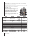
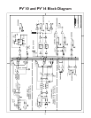
FF RR OO NN TT PP AA NN EE LL
1
2
3
4
5
6
7
8
9
10
11
12