


12
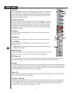
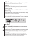
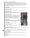
MON Send (36)
The MON Send features a
1
⁄4" TRS Z-balanced jack in the master section. This output can be used with the Tip, Ring,
Sleeve (TRS) balanced or Tip, Sleeve (TS) unbalanced connectors. The MON mix is determined by the amount of
signal being sent to the MON bus in each channel and by the Monitor master control.
EFX Send (37)
The EFX Send features a
1
⁄4" TRS Z-balanced jack in the master section. These outputs can be used with Tip‚ Ring,
Sleeve (TRS) balanced or Tip, Sleeve (TS) unbalanced connectors. The EFX mix is determined by the amount of
signal being sent to the EFX bus in each channel and by the EFX master control.
Control Room Outputs (38)
The Control Room Outputs feature two
1
⁄4
" TRS Z-balanced jacks. These outputs can be used with Tip, Ring, Sleeve
(TRS) balanced or Tip, Sleeve (TS) unbalanced connectors. The Control Room Output Level is adjusted with the
Headphone Level Control (21).
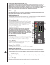
Left/Right Outputs (39)
The left/right Outputs feature two
1
⁄4" TRS Z-balanced jacks and two fully balanced XLR outputs. The
1
⁄4" outputs can
be used with Tip‚ Ring, Sleeve (TRS) balanced or Tip, Sleeve (TS) unbalanced connectors. The output level is set by
the Master Level faders (29). Both outputs can be used simultaneously.
Headphone Output (40)
The Headphone Output is a
1
⁄
4
" TRS (tip= left; ring = right; sleeve = ground). The signal sent to this output is
normally the left/right mix. When the Tape to Control Room switch is engaged, the tape input signal is added to the
left/right mix and can be monitored in the headphones.
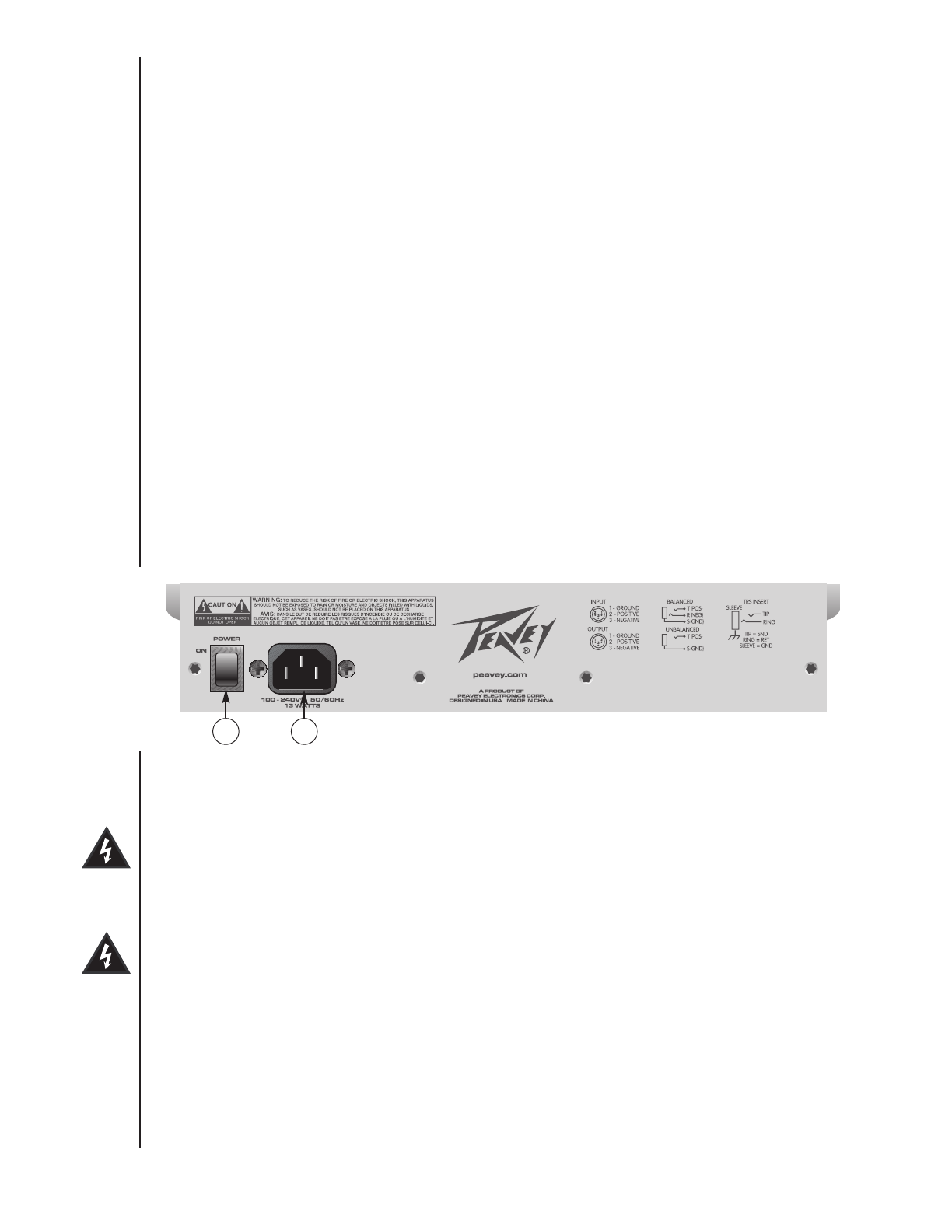
Power Switch (41)
Depressing the power switch supplies power to the unit.
Warning: The power switch in this unit breaks only one side of the line. There may be hazardous energy
present inside the mixer when the power switch is in the OFF position.
Removable Power Cord (42)
This receptacle is for the IEC line cord (included) that provides AC power to the unit. Connect the line cord to this
connector and to a properly grounded AC supply. Damage to the equipment may occur if an improper line voltage is
used (see voltage marking on unit). Never remove or cut the ground pin of the line cord plug. The console is
supplied with a properly rated line cord. If lost or damaged, replace this cord with one of the proper rating.
NOTE FOR UK ONLY:
If the colors of the wires in the mains lead of this unit do not correspond with the colored markings identifying
terminals in your plug, proceed as follows: (1) The wire that is colored green and yellow must be connected to the
terminal marked by the letter E, or by the earth symbol, or colored green or green and yellow. (2) The wire that is
colored blue must be connected to the terminal that is marked with the letter N, or colored black. (3) The wire that
is colored brown must be connected to the terminal that is marked with the letter L or colored red.
41
42