


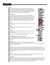

Insert
The 1⁄4” TRS connectors allow external signal processors to be inserted into the channel signal path.
Tip=Send; Ring=Return; Sleeve=Ground.
Stereo (1⁄4”) Inputs
These 1⁄4” unbalanced inputs work as a stereo line input using both jacks or as a mono input if the con-
nection is made to the left/mono input only. The A/B input selector must be in the “A” position for these
jacks to be active.
RCA Inputs
These RCA inputs work as stereo line inputs. The A/B input selector must be in the “B” position for
these jacks to be active.
A/B Switch
The A/B input selector switch expands the capability of the PV™10, PV™14, and the PV™20 mixers by
allowing two stereo sources to be connected to each stereo line input. Instead of repatching, the switch
selects which input jacks are active.
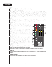
MON Send
The MON Send features a 1⁄4” TRS Z-balanced jack in the master section. This output can be used with
the Tip, Ring, Sleeve (TRS) balanced or Tip, Sleeve (TS) unbalanced connectors. The MON mix is deter-
mined by the amount of signal being sent to the MON bus in each channel and by the Monitor Master
control (19).
EFX Send
The EFX Send features a 1⁄4” TRS Z-balanced jack in the master section. These outputs can be used with
Tip‚ Ring, Sleeve (TRS) balanced, or Tip, Sleeve (TS) unbalanced connectors. The EFX mix is determined
by the amount of signal being sent to the EFX bus in each channel and by the EFX master control.
Control Room Outputs
The Control Room outputs feature two 1⁄4” TRS Z-balanced jacks. These outputs can be used with Tip,
Ring, Sleeve (TRS) balanced, or Tip, Sleeve (TS) unbalanced connectors. The Control Room output level
is adjusted with the Headphone level control (21).
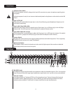
Left/Right Outputs
The left/right Outputs feature two 1⁄4” TRS Z-balanced jacks and two fully balanced XLR outputs. The
1⁄4” outputs can be used with Tip‚ Ring, Sleeve (TRS) balanced or Tip, Sleeve (TS) unbalanced connec-
tors. The output level is set by the Master Level Faders (30). Both outputs can be used simultaneously.
Headphone Output
The Headphone Output is a 1⁄4” TRS (Tip= Left; Ring = Right; Sleeve = Ground). The signal sent to this
output is normally the left/right mix. When the Tape to Control Room switch is engaged, the tape input
signal is added to the left/right mix and can be monitored in the headphones.
12
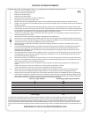
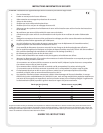
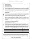
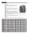
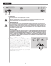
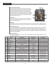
Rear Panel
34
35
37
36
38
40
39
33
41