


5
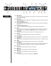
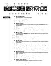
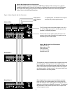
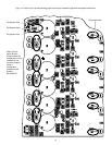
FFrroonntt PPaanneell
1 4 7 9
2 5 12 138 103
6 11 14
(1) Gain Control
This control may also be referred to as a trim control. It varies the amount of mic preamp
gain at the first gain stage.
(2) Status LED
This bi-color LED illuminates green when a -20 dBu signal is present and red when the signal
level is near clipping.
(3) Level Control (Channels 1–6)
This control adjusts the channel signal level sent to the mix buses. It functions identically on
channels 1–6.
(4) Level Control (Channels 7–8)
This level control adjusts the stereo signal sent to the mix buses for channels 7 & 8
(5) Select
The Select switch is a momentary switch that selects the stereo input signal from either chan-
nel 7 or 8. When power is applied to the SMR™821a‚ channel 7 is selected by default.
(6) Select LED
The LEDs indicate which stereo input channel (7 or 8) is feeding the mix buses.
(7) Low EQ
The Low EQ is a shelving-type active tone control. (±15 dB @ 70 Hz)
(8) Low Mid EQ
The Low Mid EQ is a bandpass (peak/notch) type of active tone control. (±15 dB @ 250 Hz)
(9) Hi Mid EQ
The Hi Mid EQ is a bandpass (peak/notch) type of active tone control. (±15 dB @ 3.1 kHz)
(10) Hi EQ
The Hi EQ control is a shelving type of active tone control. (±15 dB @ 10kHz)
(11) Level Meters
The three 5-segment LED Level Meters monitor the levels of the Left‚ Right and Aux outputs.
The 0 dB reference level corresponds to +4 dBu at its respective output connector.
(12) Left Level
The Left Level control adjusts the level of the Left output.
(13) Right Level
The Right Level control adjusts the level of the Right output.
(14) Aux Level
The Aux Level control adjusts the output of the Aux output.
(15) Power LED
This LED indicates that AC power is applied to the SMR 821a.
15