


6
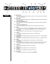
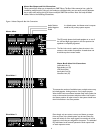
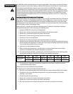
RReeaarr PPaanneell
16 18 2321
17 19 20 22 2624
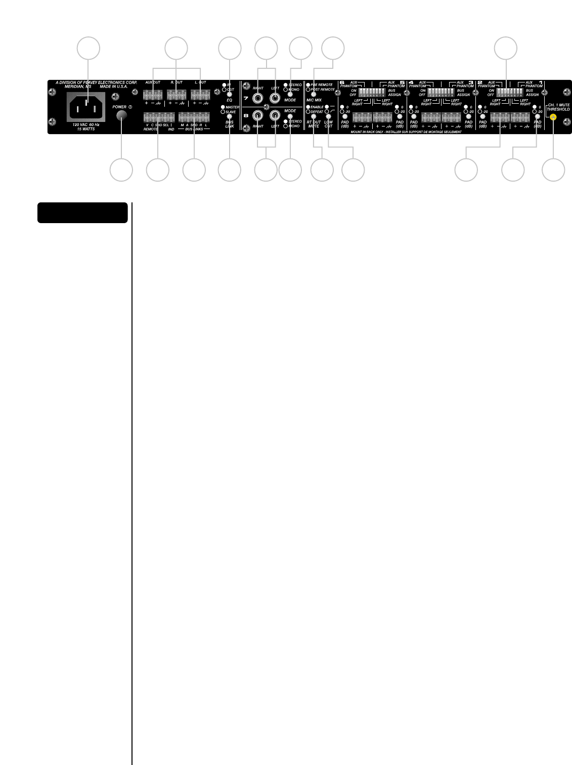
(16) AC Power Receptacle
Accepts standard IEC power cable (included).
(17) Power Switch
Applies power to the SMR™821a.
(18) Left‚ Right and Aux Outs
Main mix bus balanced outputs.
(19) Remote Connector
Used to control signal levels of the Left and Right outputs and Stereo Input Select from a
remote location.
(20) Bus Links
Stacking connector for linking multiple SMR™821a mixers.
(21) EQ Switch
Places the 4-band equalizer in or out of the Left and Right signal paths. In the Out position the
equalizer is completely bypassed.
(22) Bus Link Switch
For use with multiple SMR™821a units. This switch places the mixer in the master or slave
mode of operation.
(23 & 24) Channels 7 & 8 Input
Dual RCA connectors for stereo input sources (nominally -10 dBV).
(25 & 26) Mode Switch
Selects either stereo or mono mode for channels 7 or 8.
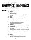
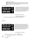
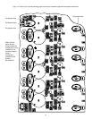
(27) Mic Mix Switch
Allows the summed signal of channels 1–6 to be routed before or after the remote Left/Right
volume control.
(28) Right Out Mute Switch
Controls the muting of the Right mix bus. When this switch is enabled‚ the Left and Right mix
buses are affected by the activity of the muting circuit. When this switch is defeated‚ only the
Left bus is affected.
(29) Low Cut Switch
This low cut filter switch has a corner frequency of 100 Hz. Enabling this switch affects
channels 1–6 only.
(30) Assignment Switches
Assigns the input channel to the Left‚ Right or Aux mix buses and enables the 48-volt phantom
power for channels 1–6.
(31) Channels 1–6 Input
Balanced microphone or line input on removable Euro-type connector.
(32) Pad Switch
The Pad switch attenuates the input signal by 20 dB.
(33) Channel 1 Mute Threshold
Adjusts the level of signal needed to trigger the muting circuitry in Channel 1.
25 27 30
28 29 31 32 33