


9
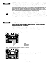
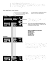
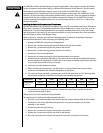
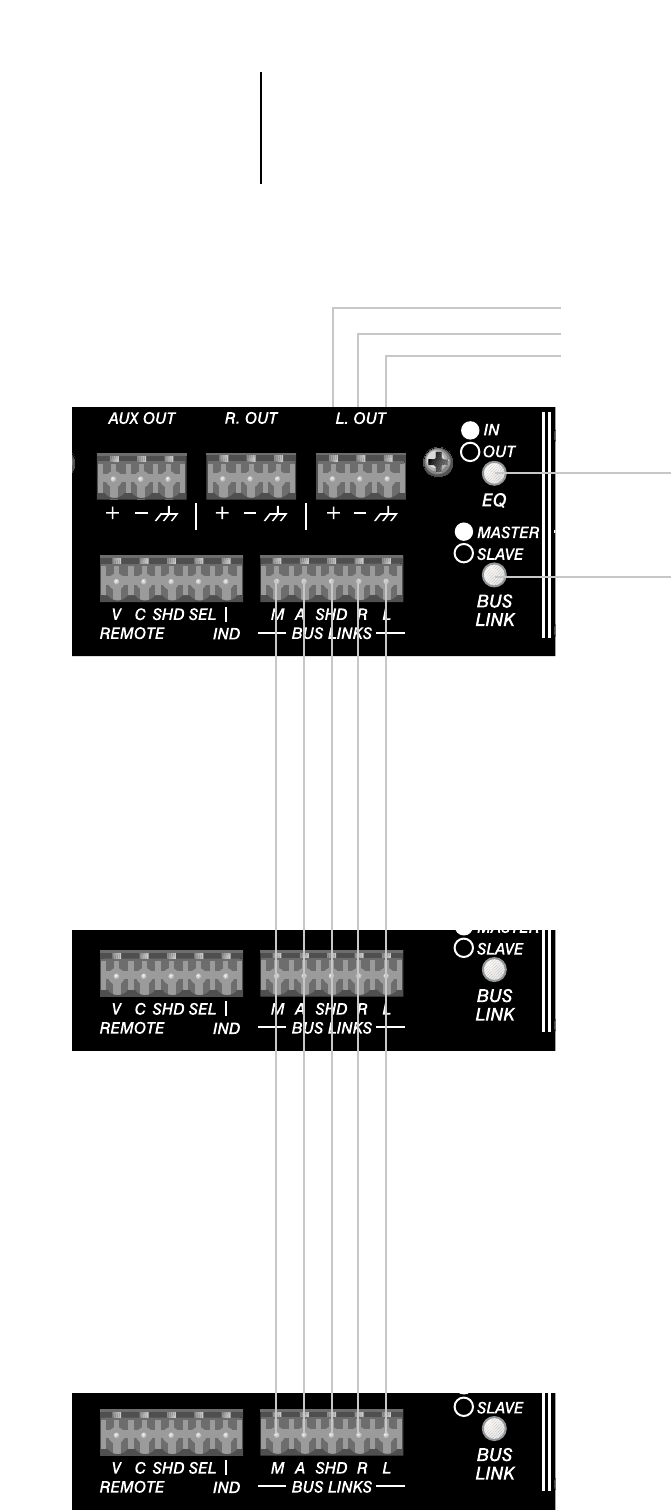
Figure 4. Master Output & Bus Link Connections
Audio Positive
Audio Negative
Shield
In a linked system‚ the Master mixer’s outputs
would be the primary system outputs.
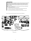
The EQ switch places the 4-band equalizer in or out of
the Left and Right signal paths. In the Out position the
equalizer is completely bypassed.
The Bus Link switch is used to place the mixer in the
master or slave mode of operation. A stand-alone unit
should always be in master mode.
To increase the number of available inputs‚ multiple mixers may
be linked together. Linking mixers is a very simple process.
Wire the Bus Links connections between each mixer. Select the
mixer to be used as the master and place its Bus Link Switch in
the Master position. All other mixers in the system should have
their link switches in the Slave position.
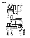
Even though only one mixer is set up as a Master‚ an output
from any mixer in the linked system may be used. Since the
buses are linked‚ all of the input signals are routed to all of the
outputs to which they are assigned in the system. The individual
EQ and Master Level controls operate the local output levels
on each respective mixer.
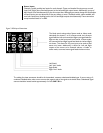
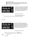
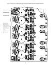
Master Bus & Mute Link Connections
Left Audio Link (L)
Right Audio Link (R)
Link Shield (Shd)
Aux Audio Link (A)
Mute Bus Link (M)
Master Mixer
Slave Mixer 1
Slave Mixer 2
Master Bus Output and Link Connections
These connections allow you to expand your SMR™821a. The Bus Links connector has 5 pins for
combining multiple units. Using a 4-pin conductor‚ shielded cable‚ you can easily connect between
two or more units wiring pin-to-pin across multiple SMR™821a mixers. Note: Use only shielded
cables. Refer to the following illustrations.