


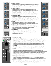
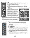

60. Power
The mixer’s main power switch. The power on LED indicator will light when the unit is powered.
61. AC Mains Input
Connect the line cord to this connector to provide power to the unit. Damage to the equipment may result if
improper line voltage is used. (See line voltage marking on unit.)
Line Cord
For your safety, we have incorporated a 3-wire line (mains) cable with proper grounding facilities. It is not
advisable to remove the ground pin under any circumstances. If it is necessary to use the equipment without
proper grounding facilities, suitable grounding adaptors should be used. Less noise and greatly reduced
shock hazard exists when the unit is operated with the proper grounded receptacles.
62. Lamp Connector
Two XLR connectors are provided for low-voltage lamps (such as the Peavey ML
™
-2 or ML
™
-3) to illuminate the
console in poorly lit environments. Each connector supplies 12V AC at 200ma between pins 1 and 2. The total
maximum load should not exceed 400ma. These connectors are short-circuit protected, with automatic reset
when a short is removed.
APPLICATIONS
The SRC
®
series of mixers were primarily designed for sound reinforcement applications, but are very
capable recording mixers as well. Here are some typical methods of hook-up:
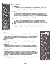
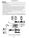
SOUND REINFORCEMENT:
1. Microphones and other low impedance sources are connected to the XLR mic inputs; high level line inputs
such as electronic musical instruments are connected to the line inputs. If problems arise because a micro-
phone either picks up an out-of-phase signal (as when using multiple drum microphones), or a very loud signal
causes clipping even at a minimum gain setting (as when close miking an amplifier or a drum head), it should
be connected to a channel with pad and polarity switches. Stereo line level sources (synth, tape, CD, etc.)
should be connected to one of the stereo channels, or to two of the mono line inputs (one panned left, the other
panned right), or to a Return input that is not used for effects.
2. The house power amplifier inputs should be connected to the main Left and Right outputs, or to the Mono out-
put. The Mono output is a blend of the Left and Right output signals (post master fader) and has its own level
control. It can be used to drive an additional amplifier that needs an independently set volume.
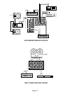
3. Connect the monitor power amplifier input to the AUX 1, 2, 3 or 4 output. Four monitors are supported, with two
additional available, if AUX 5 and 6 are also used for monitors (Pre) and not for effect sends (Post).
4. If an effect device is used, connect its input to the AUX 5 or 6 output. These outputs can also be configured as
a stereo pair (AUX 5 is the left, AUX 6 is the right) in the two stereo channels, and can be set up to feed a true
stereo effects processor.
5. The effect device outputs are connected to the Return 1, 2, 3 or 4 inputs.
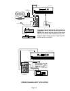
6. Connect a tape recorder to the Tape input and Tape output jacks. Care should be taken not to record on a deck
that has its outputs connected to the tape input jacks and have the tape input level control turned up, or nasty
feedback will result. If four-band equalization or a more specialized monitor send is needed, a stereo line
channel can be used for tape input (see #1 and #24). Alternatively, a stereo return can be used for tape input.
Both Return 3 and 4 have two-band EQ as well as monitor sends (to AUX 1 and 2) and full bus assignment
capability.
60
62
61
Page 10