


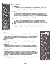
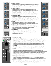
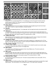

10. AUX 1/AUX 4
Adjusts the level of the channel signal (pre-EQ) that is added to
the corresponding AUX mix. These are designed to be used for
monitor sends.
11. AUX 5/AUX 6
Adjusts the level of the channel signal that is added to the
corresponding AUX mix. These are selectable Pre- or Post-EQ
Fader (#12) on all channels, and are configured in stereo
(AUX 5=L, AUX 6=R) on the two stereo channels. They can be
used as a stereo pair to drive stereo effect units. (See #14)
12. Pre/Post Fader
Establishes which signal will be present on the AUX 5 and
AUX6 sends (#11). The out position picks up the signal after the
low-cut filter, but before the four-band EQ. The depressed position
picks up the signal after the Channel Fader (#20).
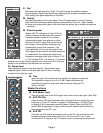
13. Pan
Sets the channel’s position in one or more stereo fields
determined by the selection of the Assignment Switches (#19).
14. Stereo Channel AUX Sends
AUX 1-AUX 4 sends are a mono mix of the left and right signals.
AUX 5 and AUX 6 are configured for stereo operation
(AUX 5=L, AUX 6=R) on these channels.
15. Balance
Adjusts the balance of the stereo signal that is sent to the
assignment select switches. Functions as a pan control for
mono signals. (See #24)
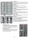
16. PFL/Clip LED
A dual-function LED that illuminates when the signal level is nearing the over-
load point, or if the PFL switch is engaged. This circuit monitors the input gain,
EQ and post-fader stages for overload. It illuminates at +19 dBu and signals
that gain or EQ boost should be reduced. (There is roughly 2 dB of headroom
remaining when it lights.) When the PFL switch (#18) is depressed, it lights
continuously to indicate that this channel has been assigned to the PFL mix.
17. Mute
Mutes the entire channel (all bus assignments and all AUX sends). The PFL
signal is not affected, and can be used to adjust the channel’s level while muted.
18. PFL
Connects the channel’s pre-fader signal to the PFL mix and switches the
headphone/control room source from the L-R mix to the PFL mix. It also connects
the PFL signal to the L-R meters to aid in the setting the input gain (#4). The
PFL/Clip LED (#16) will light when this switch is pressed to identify the PFL
source.
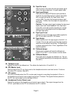
19. Assignment Switches
Selects the channel’s bus assignments (L-R, 1-2, 3-4) in pairs. The stereo
postion of the signal in the selected pair is determined by the Pan control (#13).
20. Channel Fader
Channel output level control. Sets the level sent to the Assign Switches (#19).
The optimum setting for this control is the “0” (unity gain) position.
10
11
12
13
14
15
16
17
18
19
20
Page 5