


CONNECTIONS
5
En
English
CONNECTIONS
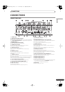
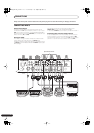
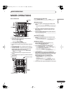
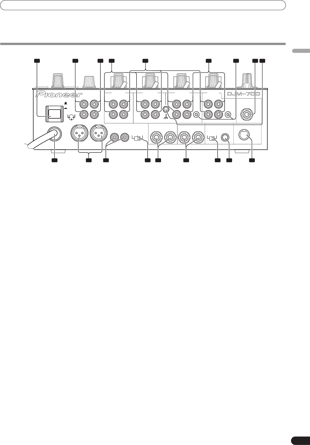
CONNECTION PANEL
1 POWER switch
2 BOOTH monitor output connectors
RCA-type booth monitor output jack.
The sound level from these connectors is controlled independently
by the
BOOTH MONITOR LEVEL
dial, regardless of the position of
the
MASTER LEVEL
dial.
3 Recording output connectors (REC)
RCA type output connectors for recording.
4 PHONO input connectors
RCA type phono level (MM cartridge) input connectors.
Do not use for inputting line level signals.
5 LINE input connectors
RCA type line level input connectors.
Use to connect a cassette deck or other line level output
component.
6CD input connectors
RCA type line level input connectors.
Use to connect a DJ CD player or other line level output
component.
7 CONTROL connectors
Ø3.5 mm mini-connector. Use to connect to the control connector
of a Pioneer DJ CD player.
When the connectors are connected, the DJM-700-S/DJM-700-K’s
fader can be used to perform start/stop on the DJ CD player.
8 Two microphone input jacks (MIC 2)
Connect microphones equipped with phone-type plugs.
9 Signal grounding terminals (SIGNAL GND)
Reduces noise when connecting an analog turntable.
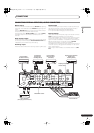
10 MIDI OUT connector
DIN type output connector.
Use to connect to other MIDI component (see P. 21).
11 DIGITAL OUT connector
RCA type digital coaxial output connector.
Master audio digital output.
12 Sampling frequency selector switch (fs 48 k/96 k)
Use to set the sampling frequency of the digital output to 96 kHz/
24-bit format or 48 kHz/24-bit format.
• Turn power off before changing this switch position.
13 RETURN connectors
Ø6.3 mm phone-type input connectors.
Use to connect to the output connectors of external effectors or
similar components.
When the L channel only is connected, the L channel input is
simultaneously input to the R channel.
14 SEND output connectors
Ø6.3 mm phone-type output connectors.
Use to connect to the input connectors of external effectors or
other similar components. When the L channel only is connected,
a L+R monaural signal is output.
15 Master output attenuator switch (MASTER ATT)
Use to attenuate the level of the master 1 and master 2 outputs.
Attenuation can be set to 0 dB, –3 dB, or –6 dB.
16 MASTER 2 output connectors
RCA type unbalanced output.
17 MASTER 1 output connectors
XLR type (male) balanced output.
• When using a cord with RCA-type plug, users are recommended
to connect the plug directly to the
MASTER 2
connectors
without using an XLR/RCA converter plug.
18 Power cord
Connect to ordinary AC outlet.
POWER
ON
OFF
BOOTH REC
L
R
L
R
L
R
L
R
L
R
PHONO LINE
CH-4 CH-3 CH-2 CH-1
PHONO LINE PHONO
SIGNAL GND
SEND
DIGITAL OUT
(MONO)
CD
RL
LINE
CONTROL
CONTROL
CD
1 GND
3 COLD
2 HOT
-6dB -3dB 0dB
MIC 2
RETURN
(MONO)
RL
RL
RL
MASTER1
MASTER2
MASTER
ATT.
48k 96k
fs(Hz)
MIDI OUT
1 2 3 4 7 8 9
101112151718 1316 14
5 6
01_DJM-700_En.book 5 ページ 2007年7月11日 水曜日 午後1時51分