13
<DRB1349>
PART NAMES AND FUNCTIONS
CD
MASTER 1
CH-2
BOOTH/
SESSION OUT
PHONO
/ LINE
RL
MASTER 2
CH-1
3 COLD
1 GND
2 HOT
CONTRAST BRIGHT
PHONO
/ LINE
PHONO
LINE
SIGNAL
GND
(MONO) (MONO)
CD
MIC
PHONO
LINE
SIGNAL
GND
CH-2 PLAYER
CONTROL
CH-1 PLAYER
CONTROL
SESSION IN
R L
R
R
L
R
L
L
SEND RETURN
R RL L
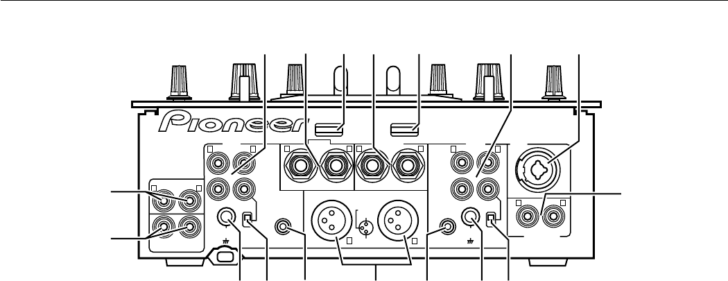
59 60 61 62 63 64 65
66
67686970717273
74
75
Rear Panel
59 CH-2 input jacks
CD
Connect to audio output from CH-2 CD player.
PHONO / LINE
Connect to audio output from CH-2 analog turntable,
cassette deck or other line signal level component.
60 External effector output jacks (SEND)
Connect to the input connectors of an external effector.
When the top panel switches (MIC SEND, CH-1 SEND, and
CH-2 SEND) are set to On, these jacks output the MIC, CH-1,
and CH-2 signals to the external effector.
When using an effector with a monaural input, connect it to
the L channel output only. The signal actually sent to the
effector will represent a mix of L and R signals.
61 Touch panel screen contrast control (CONTRAST)
Use to adjust the top panel’s touch panel contrast.
62 External effector return jacks (RETURN)
Connect to the output connectors of the external effector.
When using an effector with monaural output, connect only
to the L channel input. The signal received from the effector
will be input to both L and R channels.
63 Touch panel backlight control (BRIGHT)
Use to adjust the top panel’s touch panel backlight
luminance.
64 CH-1 input jacks
CD
Connect to the audio output of the CH-1 CD player.
PHONO / LINE
Connect to audio output from CH-1 analog turntable,
cassette deck or other line signal level component.
65 Microphone input jack (MIC)
Connect to a microphone with XLR type or PHONE type plug.
When applying effects to the microphone sound, set the top
panel’s CH-1 input selector switch (MIC–PHONO 1/LINE 1–
CD1) to the [MIC] position.
66 Session input jacks (SESSION IN)
When using multiple mixers simultaneously, connect the
other mixer outputs to these jacks.
67 CH-1 PHONO/LINE selector switch
Use to set the input sensitivity at the CH-1 PHONO/LINE
connectors. The [PHONO] position supports an MM type
cartridge.
* When no analog turntable is used, set this switch to the
[LINE] side.
68 CH-1 signal ground (SIGNAL GND)
Connect to the CH-1 analog turntable’s ground wire. Note
that this is not meant as a safety ground.
69 CH-1 PLAYER CONTROL jack
When a Pioneer DJ CD player is connected to the CH-1 CD
jacks, a special control cord can be used to connect this jack to
the player’s control jack, thus enabling the fader start function.
70 MASTER 1 jacks
XLR type balanced output. Connect to the power amplifier’s
balanced input jacks.
71 CH-2 PLAYER CONTROL jack
When a Pioneer DJ CD player is connected to the CH-2 CD
jacks, a special control cord used to connect this jack to the
player’s control jack, thus enabling the fader start function.
72 CH-2 PHONO/LINE selector switch
Use to set the input sensitivity at the CH-2 PHONO/LINE
connectors. The [PHONO] position supports an MM type
cartridge.
* When no analog turntable is used, set this switch to the
[LINE] side.
73 CH-2 signal ground (SIGNAL GND)
Connect to the CH-2 analog turntable’s ground wire. Note
that this is not meant as a safety ground.
74 BOOTH/SESSION OUT jacks
Connector jacks for booth monitor output. When using this
unit in tandem with another mixer, connect these jacks to the
other mixer’s session input jacks.
75 MASTER 2 jacks
RCA type unbalanced output. Connect to the power
amplifier’s unbalanced input jacks.


