


8
Tools and materials you will need:
Soldering iron
Desoldering iron or other suitable desoldering equipment
Phillips screwdriver
Wire cutters
Rosin-core solder
CAUTION:
• Do not use desoldering braid because it may damage the solder pads on the BusCard or input board, and it also might not adequately
remove solder.
• The UF-3 contains active components which can be damaged by electrostatic discharge (ESD). Be sure to practice standard ESD
precautions and always ground yourself and your workstation before handling exposed circuit cards.
• Preparing the input board for installation of the UF-3 involves removing solder from feed-through holes on a two-sided circuit card.
Excessive heat can easily damage the solder pads you will be working on. Proper equipment and experience with desoldering delicate
PC board circuitry is essential to successfully perform the following procedure.
• Please contact the QSC Technical Services Group if you feel you might not be qualified to perform the installation yourself.
•
One last warning:
damage caused by an improper installation will void the warranty.
Installing the UF-3 on a BusCard
It is easier to configure and install the UF-3 Universal Filter with the BusCard removed from (or not yet installed in) the amplifier.
Turn off the amplifier and unplug it from the AC. Allow about 10 minutes or longer for the internal voltages to bleed down before you open the
amplifier chassis.
If the UF-3 is to be installed on a BSC-6 BusCard (for the PowerLight 3.4, 3.8
X
, or 4.0), snap off the breakaway section of the UF-3 circuit board
by flexing it at the pre-scored line.
Make sure you insert the UF-3 card on the correct side of the BusCard. Insert the UF-3 fully into the holes on the BusCard. Solder all 22 pins to
the BusCard; make sure you don’t create any solder bridges. Then install the BusCard in the amplifier; see the BusCard instructions for details.
Installing the UF-3 on an input card
Turn off the amplifier and unplug it from the AC. Allow about 10 minutes or longer for the internal voltages to bleed down before you open the
amplifier chassis. Disconnect all cables from the amplifier’s input panel.
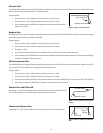
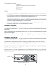
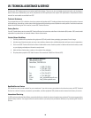
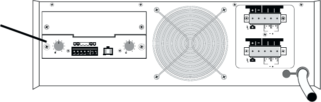
Position the amplifier so the rear of the chassis is facing you. The input panel is located on the left side of the rear panel. See Figure 11.
Begin the installation by locating and removing the screws securing both the upper blank and lower input panels to the rear side of the chassis
(two screws on each mini panel). The upper blank panel will simply drop off when its screws are removed.
Gently pull the lower input panel out from the amplifier. Once it is removed, you will notice a ribbon cable connecting the input PC board to the
amplifier. Disengage the locking wing clamps on the ribbon header and carefully remove the ribbon head from the socket on the board. Now the
input panel assembly is completely free from the amplifier.
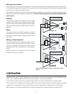
Next, desolder and remove the wire jumper pairs W305/W306 and W405/W406 (W303/W304 and W403/W404 on MXa Series amplifiers).
Under where the jumpers were are two rows of solder pad holes, one with 10 holes and another with 12. These make up the “Mini-Slot,” in which
the UF-3 mounts. See Figure 12.
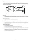
CH1
CH2
CH1
CH2
BRIDGE
MONO
BRIDGE
MONO
LOW IMPEDANCE
LOW IMPEDANCE
DIR. OUTPUT
DIR. OUTPUT
ISOL.OUTPUT
ISOL.OUTPUT
AUDIO TRANSFORMER
AUDIO TRANSFORMER
70V
70V
25V
25V
100V
100V
070100
070100
0
0
-dB -dB
10 10
88
66
44
22
24
24
18 18
14
14
STEREO
12
12
CH2 INPUT CH1
CH2 CH1
PARALLEL BRIDGE LEVELLEVEL
GROUND
INPUT
Input card
Figure 11—Location of the input card