


6
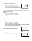
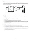
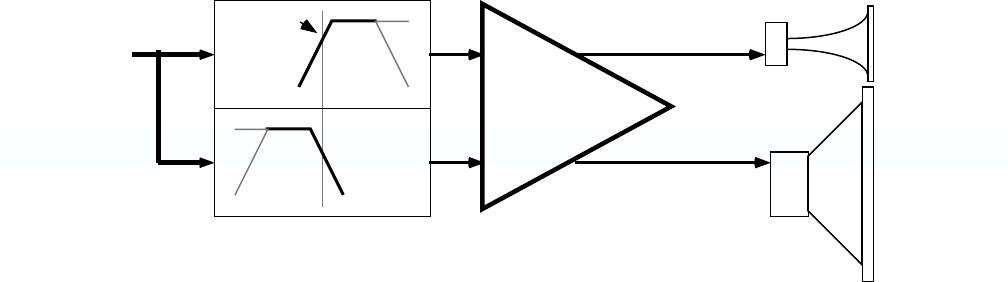
2-Way Active Crossover
This configuration routes the frequencies below a particular frequency to amplifier Channel 1, which shall drive the low-frequency speakers, and
the frequencies above to Channel 2, which shall drive the high-frequency speakers. Using the UF-3 as a crossover requires that you drive both
amplifier inputs with the same full-band signal.
Program settings:
1. On the input module, set the amplifier mode to parallel. Alternately, you could use a Y-cable to provide the same signal to both channel
inputs.
Steps 2 through 5 configure Channel 1.
2. Jumper J101 to enable Channel 1’s low-pass filter (across pins 2 and 3).
3. No jumper on J103.
4. Insert a resistor network into RN102 that is appropriate to the desired crossover frequency.
5. If you need subsonic filtering, set a jumper on J102 to enable Channel 1’s high-pass filter (across pins 2 and 3) and insert a resistor
network into RN104 that corresponds to the roll-off frequency you desire. If you do not want subsonic filtering, set J102 to bypass the
high-pass filter (across pins 1 and 2).
Steps 6 through 9 configure Channel 2.
6. Set J202 to enable Channel 2’s high-pass filter.
7. Insert a resistor network into RN204 that is appropriate to the crossover frequency you set in #4.
8. If you need equalization for a constant-directivity horn, set a jumper on J203 for the amount of boost you need. If you do not want CD
horn equalization, do not place any jumper on J203.
9. If you need ultrasonic filtering, set a jumper on J201 to enable Channel 2’s low-pass filter (across pins 2 and 3) and insert a resistor
network into RN202 that corresponds to the desired roll-off frequency. If you do not want any ultrasonic filtering, set the jumper on
J201 to bypass the low-pass filter (across pins 1 and 2).
F
c
Channel 2
Channel 1
Amp
HF Driver
LF Driver
Channel 2
Channel 1
SPA-2
Figure 9—UF-2 as a 2-way active crossover