


2
III. PROGRAMMING THE UF-3
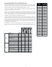
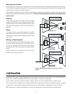
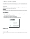
The UF-3 circuit board has six 3-pin headers and four SIP resistor network sockets (see Figure 2). All are used for programming the module. The
circuitry for the two channels is identical, so the headers and sockets are divided between them: those designated by a three-digit number starting
in a “1” (headers J101, J102, and J103; and SIP resistor network sockets RN102 and RN104) are for Channel 1, while those with a three-digit
number starting in a “2” are for Channel 2. The following instructions will use an “x” in place of the first digit, except where a specific channel
reference is necessary.
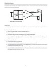
Notes on Stereo, Bridged, or Parallel
Operation
Except for specialized bi-amp models such as the
PowerLight 1.5
X
, 1.6
HVX
, or 3.8
X
, the amplifier in which the
UF-3 is installed has a switch for setting the operating
mode of the amplifier, i.e., stereo, parallel mono, or
bridged mono. In the signal flow, the UF-3 accessory is
located after the switch, so you must configure both
channels of the UF-3 accordingly, whatever the operating
mode. Usually you would use identical settings on both
channels in stereo or parallel mode, depending on the application. If the amplifier is in bridged mode, bypass
Channel 2 of the UF-3 and use the Channel 1 input and processing only.
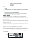
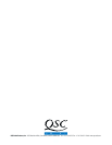
Bypassing the Filtering
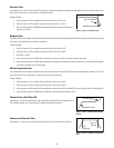
To completely bypass the filtering circuitry of a channel, set the jumpers on both Jx01 and Jx02 across pins 1 and
2, which are the upper two pins on their headers (see Figure 3). Note: If you neglect to place jumpers on either
header, no signal will pass on that channel.
RN102
( of low-pass filter)
f
RN104
( of high-pass filter)
f
RN204
( of low-pass filter)
f
RN202
( of high-pass filter)
f
(low-pass bypass/enable)
J101 J102
(high-pass bypass/enable)
J103
(CD horn EQ)
(low-pass bypass/enable)
J202 J201
(high-pass bypass/enable)
(CD horn EQ)
J203
1
2
3
1
2
3
1
2
3
1
2
3
Channel 1 Channel 2
1
2
3
1
2
3
Pins 1 & 2
shorted together
Pins 2 & 3
shorted together
1
2
3
ycneuqerF
)zH(
rotsiserPIS
eulavkrowten
08K021
001K28
021K86
061K65
002K74
052K33
005K81
008K21
0001K2.8
0021K8.6
0061K6.5
0002K7.4
0052K3.3
0005K8.1
0008K2.1
00061065
00002074
Programming the Low-Pass Filter
To use the low-pass filter, set the jumper on Jx01 across pins 2 and 3, which are the lower two pins on
their header. If, however, you do not wish to use the low-pass filter and want to bypass it instead, set the
jumper across pins 1 and 2.
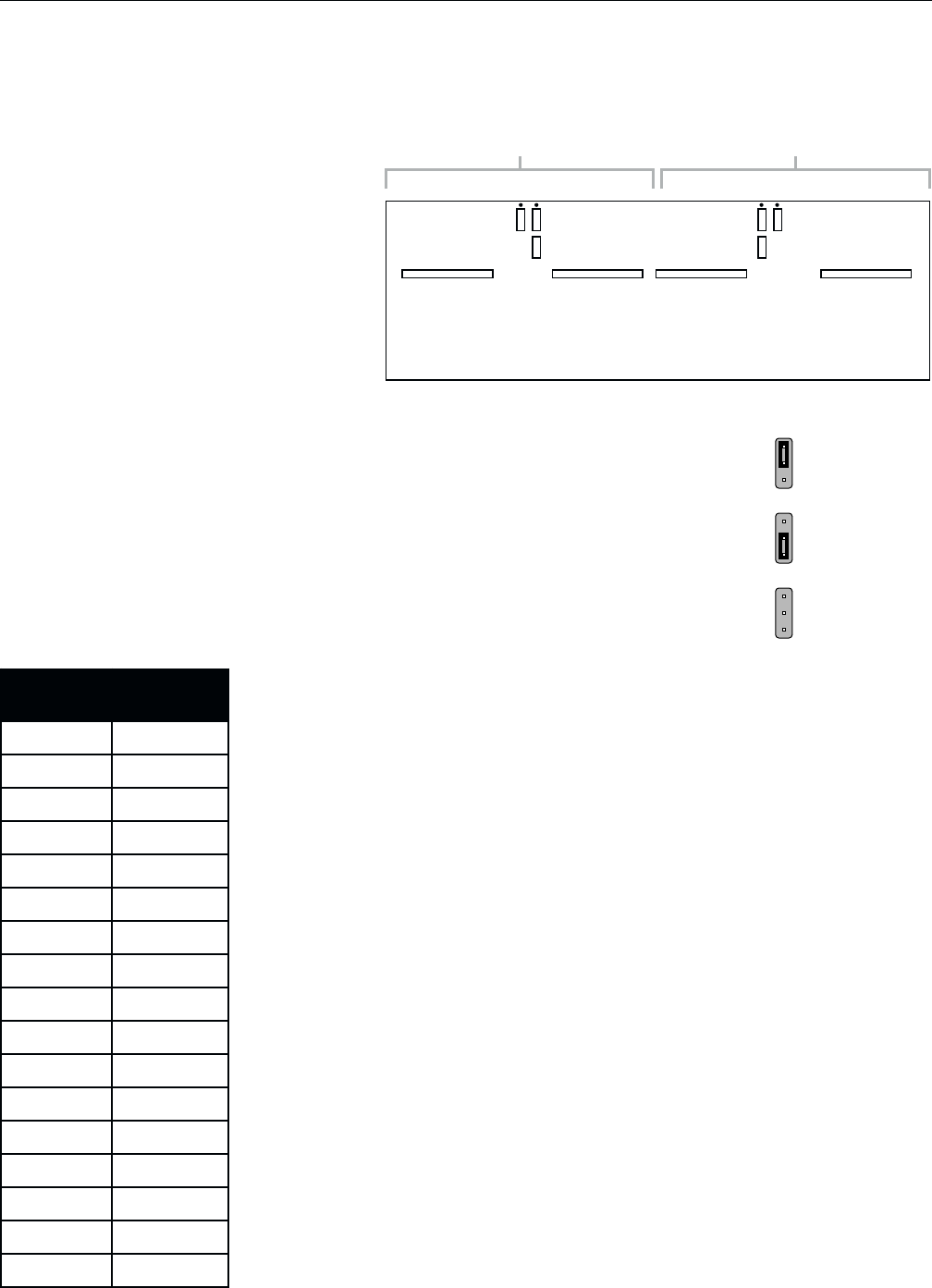
To set the corner frequency (at which the output is 6 dB down) of the low-pass filter, choose the appropriate
value for RNx02; use the table at left.
If there is a resistor network already installed in the socket, carefully pull it straight out. Insert the pins
of the new resistor network into the socket holes and carefully press the network into the socket. Be
careful to avoid bending the pins of the resistor network. Orientation of the resistor network is
unimportant, as long as all eight pins are well seated in the socket.
Figure 2—UF-3 Circuit board jumper and resistor network locations
Figure 3—Jumper positions