


MX10 Page 20
and S4.
❒ 133. Install the next two yellow LEDs (D11 and D23) Check the long lead
side!
❒ 134. Install two more yellow LEDs (D13 and D24). Again check the long
lead side.
❒ 135. Install the last of the yellow LEDs to go in the meter (D14 and D25).
There should be two left over for the microphone indicators.
❒ 136. Install the first of the red LEDs to go in the meter just to the right of
the yellow LEDs (D15 and D26). Make sure the long leads are oriented
correctly.
❒ 137. Install the next two red LEDs. (D16 and D27) Long leads!
❒ 138. Install the last of the red LEDs and the last of the LEDs to go in the
meter (D17 and D28). Make sure the longer leads are facing away from
the switches!
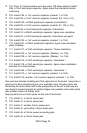
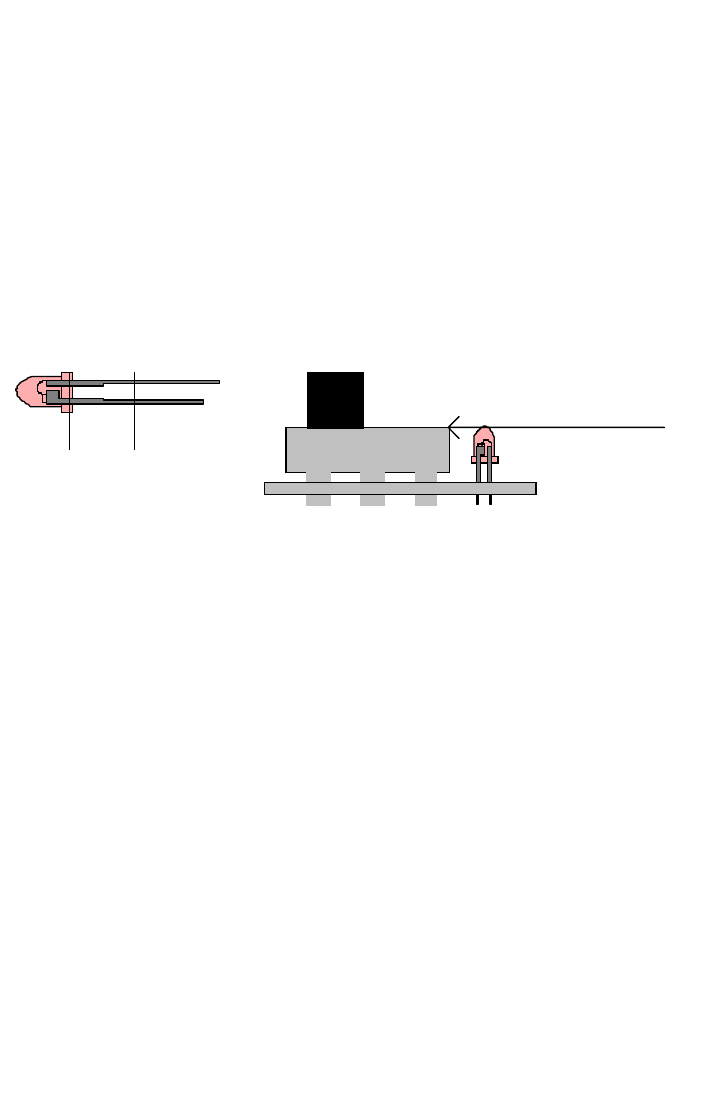
❒ 139. Now we will install the remaining yellow LEDs that indicate whether
or not the microphone is in or out. Install D12. The long lead in this case
faces in the opposite direction of the LEDs in the meter. (Note the triangle
side on the parts layout). Again this LED is mounted at the same height as
the switch.
❒ 140. Install D3, the other yellow LED. Again note that the long lead is in
the opposite direction as those in the meter (triangle side).
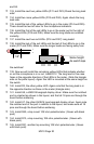
❒ 141. Install U8, a LM3915 bargraph display driver. Make sure the notched
end is oriented as shown in the layout, and that all 18 pins are through the
board before soldering.
❒ 142. Install U7, the other LM3914 type bargraph display driver. Again note
the notched end of the part in relation to the layout, and make sure all 18
pins are through the board before soldering.
❒ 143. Install R40, a top mount 10K ohm potentiometer. (Green with black
post)
❒ 144. Install R13, a top mounting 10K ohm potentiometer. (Green with
black post).
❒ 145. Install R31, another top mounting 10K ohm potentiometer. (Green
with black post).
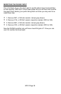
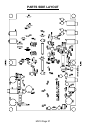
A
K
1/8"
Same height
As switch tops