


MX10 Page 7
circuits. The earphone amplifiers LM386s have quite a bit of kick to them, which
should be more than enough to out power most DJ systems.
The peak hold meters serve the function of displaying peak amplitudes in your
audio so your eye can see them. Normally a short duration pulse such as a
drum beat or strum of a guitar has a very short time duration for the initial
higher power sound. If we didn’t use a peak hold circuit, your eye would be
hard pressed to see the LEDs blink on the bargraph, or in the case of an analog
meter, the mechanical weight holds back the needle from going to the actual
peak.
The peak hold circuit consisting U4:A and U4:B combined with D6, R43, C14,
D19, R60, and C17 takes an instantaneous peak and stores it in the two 10uF
capacitors. The resistors then discharge the capacitors at a slow rate. These
capacitors and resistors extend the peak long enough in duration so that your
eye can see it. The function of the diode is to DC rectify the incoming audio
signals since we only are interested in the positive going signals. If we did not
DC rectify the signal, we would constantly positively charge the capacitor on a
positive pulse, then negatively charge it on a negative pulse. The net result
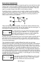
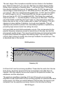
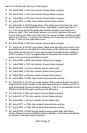
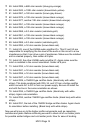
would be a meter that just barely twinkled at you. Here is an example of what a
peak hold circuit does for you. The dark gray is the original signal, and the light
gray is the peak hold signal. As you can see the light gray stays at a higher
amplitude for a longer period of time.
The power supply for the MX10 is a little different than you may have expected.
12VAC is plugged into J8, the power jack. The 12VAC is then rectified to DC
using diodes D29, 31, 34, and 35. This is then “smoothed” out using C30, which
averages out most of the bumps and lumps out of the power supply noises.
VR1, a voltage regulator takes out the rest of the bumps and lumps, and gives
us a clean smooth +12 VDC power source with very little noise. U8:C is then
set up to give us a buffered, regulated split supply voltage. The output of this
opamp is now used to generate a ground, while the supply voltages are now +5
and -5 volts (closer to +6 and -6) in reference to this “ground”. This method is
an easy way to get a split supply from a single supply such as ours.
TIME
AMPLITUDE