PA-1 • 14
A NOTE FOR EXPERIENCED BUILDERS ON LINEAR OPERATION FOR
SSB, AND OTHER EMISSION TYPES:
Please undertake this conversion ONLY if you understand the theory and
practice involved. Otherwise, please get help from another ham experienced in
amplifier design. This conversion changes the power transistor form Class C to
"biased on" Class B operation. The transistor is not under warranty as we've
already explained, and improper configuration can easily damage it.
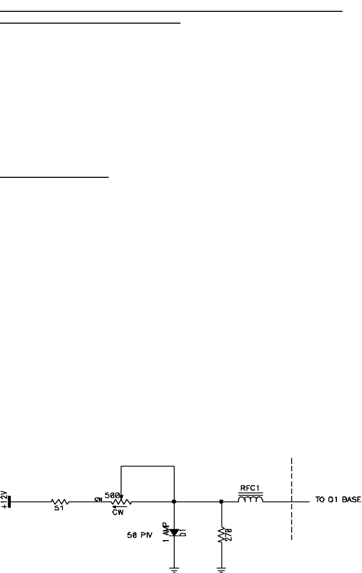
Linear operation configuration consists of applying 12 volts DC through a
simple 4-part adjustable circuit, through the original RF choke to the base of RF
power transistor Q1, carefully checking Q1's collector current right from the
start.
CONVERSION STEPS:
❒ 1. Lift the ground side of the RF choke.
❒ 2. Solder a 1 amp diode's cathode lead (banded end) directly to the
emitter-ground connection of the RF power transistor. Keep this cathode
very short so that the diode can temperature-track the transistor.
❒ 3. Connect the following to the lifted end of the RF choke, keeping all wires
as short and neat as possible:
- anode lead of diode
- one end of a 270-ohm resistor
- one end and center of a 500-ohm trimmer pot
❒ 4. Solder the other end of the 270 ohm resistor to the PA1 groundplane foil.
❒ 5. Connect the remaining end of the 500 ohm pot through a 51 ohm resistor
to a neatly routed wire to the +12 volts DC input to the PA1.
❒ 6. Set up a 0-100 milli-ammeter or VOM to monitor Q1's collector current.
❒ 7. Keeping your tests short, adjust the 500 ohm pot for about 50 mA of
collector current. Do not exceed 100 mA!


