


9
Controls and Functions
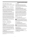
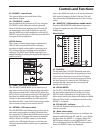
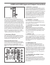
42 - PHONES – control knob
This control adjusts the overall level of the
Headphone Output.
43 – PFL DEFEAT – switch
You can defeat all the channels in PFL by using the
PFL DEFEAT switch. When the switch is pressed
down it will illuminate, indicating the PFL and AFL
are temporarily turned off. At that point you will
hear the MAIN mix in the headphones until the PFL
DEFEAT is turned off and you will now hear the SOLO
bus again in the headphones.
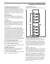
USB I/O Section
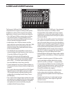
The L series consoles incorporate a sophisticated
USB I/O with on board AD and DA converters
providing a digital audio path for connecting to a
PC running most any recording and/or playback
software. The INPUT and ASSIGN switch give you
added flexibility in routing the digital audio signal to
and from the PC.
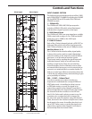
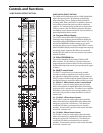
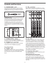
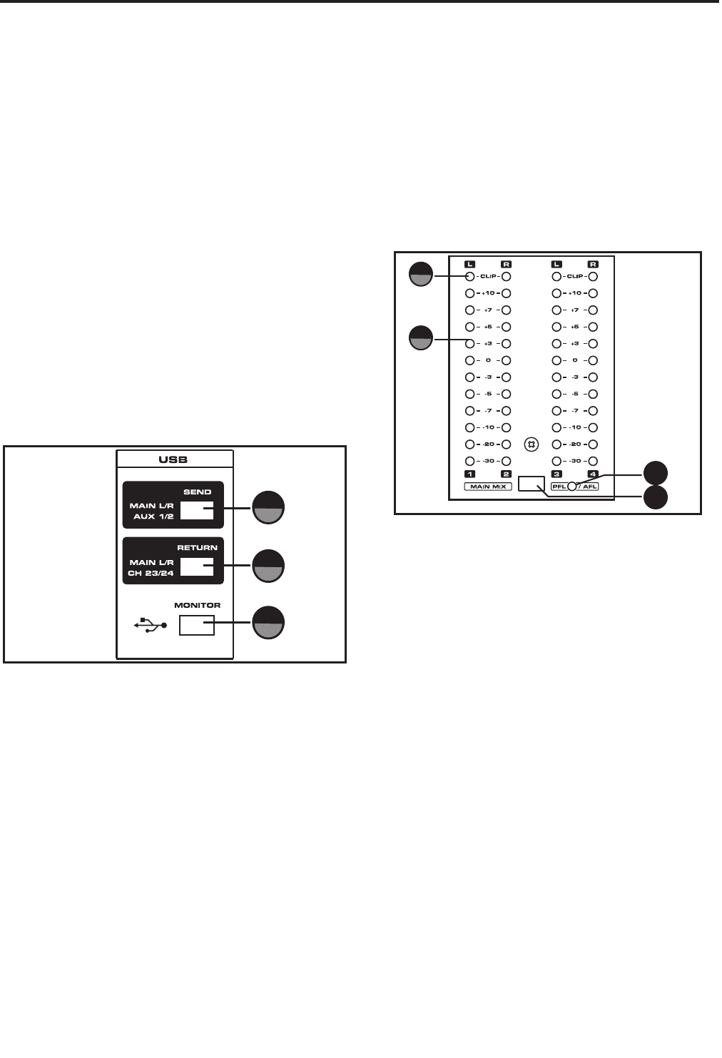
44 – SEND – USB input send switch
The USB INPUT switch allows you to select one of
two stereo (or two channel) signal paths to feed the
USB output to send to the connected PC. When the
INPUT switch is in the up position, the USB signal will
feed from the MAIN left right mix. When the INPUT
switch is in the down position, the USB signal will
feed from the AUX 1 and AUX 2 buses which enables
you to create a unique mix to send to the PC.
45 – RETURN – USB return switch
The USB RETURN switch allows you to select one of
two stereo return paths to receive USB audio from
the connected PC. When the ASSIGN switch is in the
up position, the USB signal will return to the MAIN
mix bus. When the ASSIGN switch is in the down
position, the USB signal will return to the last pair
of stereo channels which enables you to playback a
recorded
46
44
45
track in the MAIN mix, and you can use the channels
AUX sends to feed any of the AUX buses. This will
let you hear the USB playback tracks in the monitor
mixes.
46 – MONITOR – USB headphone enable switch
Press the USB MONITOR switch down if you want
to hear the signal from the USB return in the
headphones.
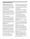
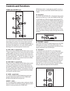
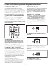
Meter Section
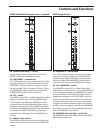
47 - CLIP LEDs
The left and right CLIP LED’s illuminate when the
signal from the selected bus is beginning to reach
a level where distortion occurs. If the CLIP lights
stay on, your mix is too hot and you need to lower
the level control. It is okay for the PEAK light to
occasionally light, however they should go off
quickly and not stay on.
48 - LED VU METER
The OUTPUT LEVEL METER allows you to monitor
the level of the signal, which is being sent to the
MIX OUT jacks. Depending on the position of the
Meter select switch, the meters will display the MAIN
MIX with PFL and AFL, or display the level from the
GROUP 1–4 outputs.
49 - PFL/AFL LED - indicator
The LED will illuminate whenever any PFL or AFL
switch is pressed.
50 – Meter select switch
The Meter select switch allows you to configure the
Meters for MAIN MIX with PFL and AFL, or to display
the level from the GROUP 1–4 outputs. When the
METER select switch is up, the MAIN MIX, PFL and
AFL are displayed. When the METER select switch is
down, the GROUP output are displayed.
47
48
49
50