


13
23/24
LINE 24
LINE 23
24
23
6
7
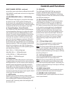
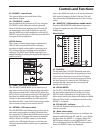
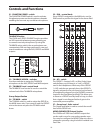
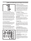
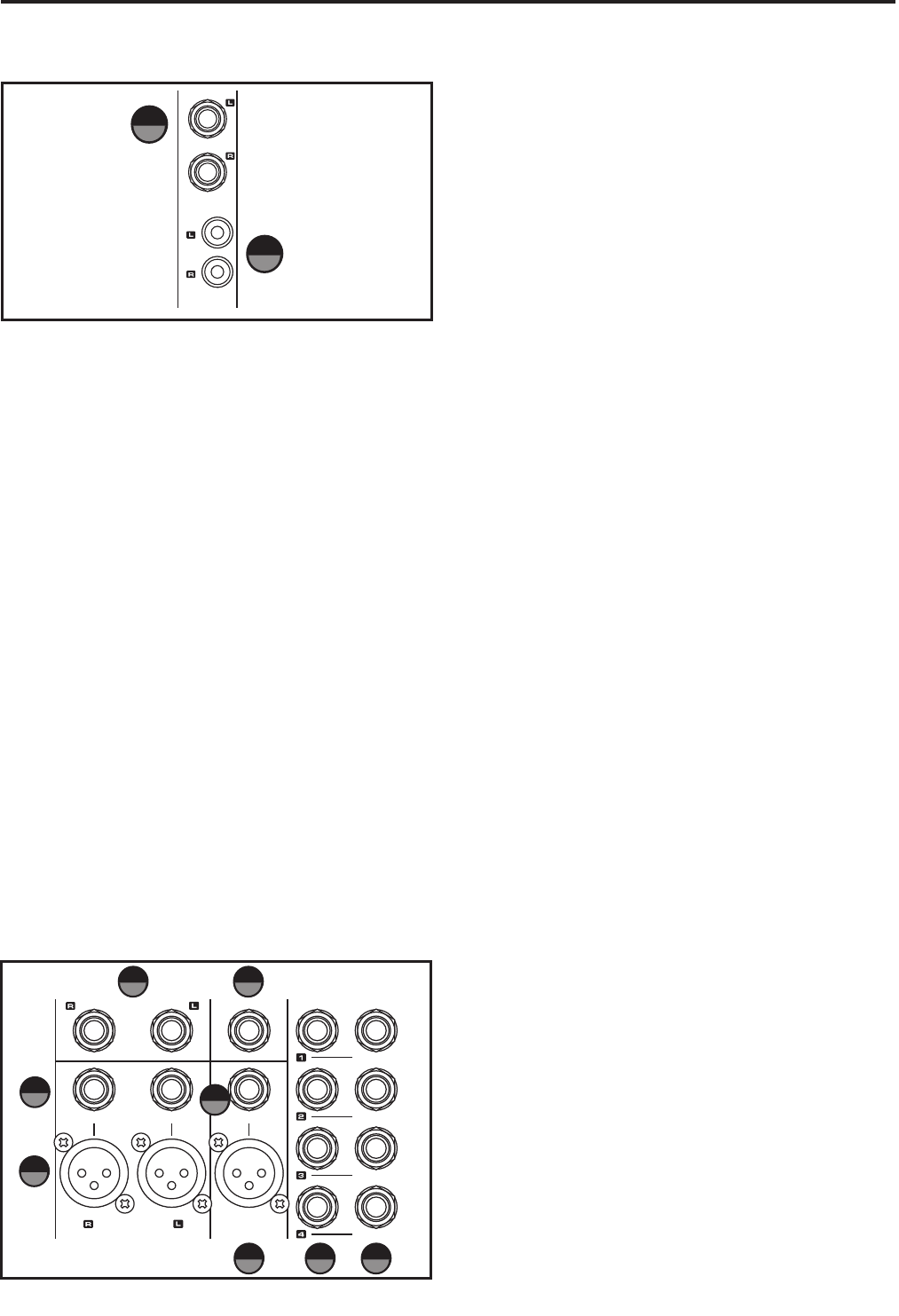
6 - Stereo Inputs - 1/4-inch jacks
The L Series second two stereo channels have 1/4-
inch jacks for connecting stereo line level sources.
For stereo inputs, use the LINE L to connect the left
channel and the LINE R to connect the right channel.
If you are using the inputs for a mono line input, use
the LINE L input, (channels 17 or 19 on the L2400
and channels 25 or 27 on the L3200), only so that
the signal feeds both the right and left Main mix bus.
Use these inputs to connect high impedance micro-
phones, synthesizers and drum machines. The LINE
inputs have a nominal operating level of -40dBV
through - 10dBV. TRS phone jack connector pin-out
- Sleeve: Ground, Tip: Hot (+), Ring: Cold (-)
7 - Stereo Inputs - RCA jacks
The L Series second two stereo channels also have
RCA connectors that accept signals from stereo line
devices. The RCA line level inputs have a nominal
operating level of -40dBV through - 10dBV.
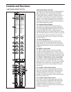
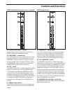
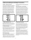
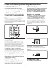
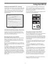
Master Input and Output Section
The TXM mixer's Master Input and Output section
has the connectors for interfacing the FOOTSWITCH,
MAIN OUT, MAIN OUT B, MAIN INSERT POINTS,
GROUP OUTS, GROUP INSERT POINTS, and the AUX
OUT’s.
MONO OUT
FOOT SWITCH
INSERT
INSERT
GROUP OUT
MAIN OUT
MAIN B
INSERTINSERT
INSERT
INSERT
INSERT
8
12
13
14 15
9
10
11
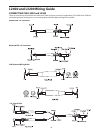
8 - MAIN OUT B - 1/4-inch jacks
In a live sound application, you can drive a second
speaker system using the MAIN OUT B outputs con-
nected to a power amplifier or powered speakers. In
a recording application, the MAIN OUT B outputs are
used to connect a stereo device such as computer
sound card, MP3, or cassette recorder. The signal at
the MAIN OUT jacks follows the MAIN OUT B level
control knob allowing you to set a different level
to the recorder. TR phone jack connector pin-out -
Sleeve: Ground, Tip: Hot (+).
9 – FOOTSWITCH - 1/4-inch jack
With a footswitch connected to this jack, you can
turn on and off the on-board digital effects by sim-
ply stepping on the footswitch.
10 - MAIN INSERT (Left and Right) - 1/4-inch Send
and Return jack
Send and return patch point on TRS (TIP/RING/
SLEEVE) jack for interfacing external effects proces-
sors on Left and Right MIX bus. The signal is sent on
the tip (the Send) and returns (the Return) on the
ring of the connector.
11 - MAIN OUT – XLR
In a live sound application, you can drive a speaker
system using the MAIN OUT outputs connected to a
power amplifier or powered speakers. The signal at
the MAIN OUT jacks follows the MAIN volume fader.
XLR connector pin-out - Pin 1: Ground, Pin 2: Hot (+),
Pin 3: Cold (-)
12 - MONO/SUB OUT- XLR
The Left and Right Mix outputs are summed
together and sent to the MONO/SUB output. The
volume of the Mono signal can be adjusted using
the MONO/SUB OUT level fader control and used to
feed a speaker zone in a fixed installation. For added
flexibility, the MONO/SUB OUT can be used to feed
a subwoofer using the onboard variable Low Pass
Filter. XLR connector pin-out - Pin 1: Ground, Pin 2:
Hot (+), Pin 3: Cold (-)
13 - MONO INSERT (Left and Right) - 1/4-inch
Send and Return jack
Send and return patch point on TRS (TIP/RING/
SLEEVE) jack for interfacing external effects proces-
sors on MONO MIX bus. The signal is sent on the tip
(the Send) and returns (the Return) on the ring of
the connector.
L2400 and L3200 Input and Output Connections