


3
Controls and Functions
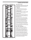
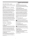
INPUT CHANNEL SECTION
The following section details each part of the L2400
and L3200’s INPUT CHANNELS including the 3-BAND
EQ, the MONITOR and EFX sends, PAN, GAIN and
VOLUME controls.
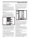
1 – SIGNAL LED
The L2400 and L3200’s MIC/LINE pre-amp also
includes a SIGNAL LED which, when illuminated,
indicates that a signal is present at the input.
2 - GAIN Control Knob
The L2400 and L3200’s pre-amp stage has a variable
GAIN control with a range of -6 to -50dB on the MIC
input and +14 to -30dB on the LINE input.
3 - LOW CUT Switch
Each of the L Series’ channels include a LOW CUT (or
high pass) filter which rolls off the low frequencies
from 75Hz and below at the rate of 18dB per octave.
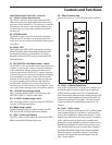
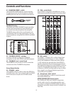
Auxiliary Buses ( 4 - 8 )
The L Series include several auxiliary signal paths,
or buses, that can be used to create independent
mixes for sending to the internal or external effects
processors, or to an external monitor system.
These buses start by sending the signal from each
individual channel, which is set with one of the
auxiliary control knobs. Then, the mix of all the
channels auxiliary level is ultimately sent to either
an internal effects processor, or to an output jack to
connect to an external effect or monitor system. To
help you control your effects and monitor mixes, the
L series has six auxiliary buses, with switching to give
you a possibility of 8 mixes.
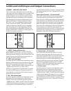
PRE….? POST….? What’s That?
In order to operate your mixer correctly, it is
important to understand the concept of PRE and
POST fader sends. An auxiliary bus that is set up
as PRE Fader routes, or sends, the signal to its
output from a point in the channels’ circuit that is
electronically before the channel Fader. That means
the channel Fader has no effect on the PRE aux
level. A Pre Fader send is what you want to use for
a monitor mix, so when the level is changed for
the mix in the main PA speakers using the channel
Fader, the level in the monitor set by the aux control
knob remains the same. An auxiliary bus that is set
up as POST Fader routes, or sends, the signal to its
output from a point in the channels’ circuit that is
electronically after the channel Fader.
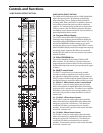
1
GAIN
LOW CUT
75Hz
18dB/OCT
PAN
PEAK
PFL
1-2
3-4
MAIN
SIGNAL
CH 1
CH
1
10
-10
-30
5
0
5
10
15
20
30
40
PRE /
POST
AUX 1
AUX 2
AUX 3
AUX 4
EFX 1
EFX 2
AUX 5
AUX 6
FREQ
Hz
LF
80
MF
HF
12K
800
100 8k
2
1
3
4
5
6
7
8
9
10
11
13
12
14
15
16
17
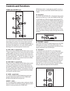
SIGNAL
BALANCE
GAIN
0
-30
-20
-10
+20
CH 17/18
CH
17/18
LO-MID
500
LF
80
HI-MID
3K
HF
12K
PRE /
POST
AUX 1
AUX 2
AUX 3
AUX 4
EFX 1
EFX 2
AUX 5
AUX 6
25/26
PEAK
PFL
1-2
3-4
MAIN
10
5
0
5
10
15
20
30
40
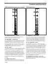
1 to 24 on the L3200
1 to 16 on the L2400
25/26 to 31/32 on the L3200
17/18 to 23/24 on the L3200
Mono Inputs Stereo Inputs