


20
Bass Guitar
Rhythm Guitar
Lead Guitar
Keyboards
SIGNAL FLOW
SIGNAL FLOW
SIGNAL FLOW
SIGNAL FLOW
S
A
M
S
O
N
R
2
1
S
A
M
S
O
N
R
2
1
SIGNAL FLOW
SIGNAL FLOW
Vocal Vocal
Signal Processor
Direct Box
Signal Processor
Stereo Signal
RIGHT CONTROL ROOM
OUTPUT
LEFT CONTROL
ROOM
OUTPUT
LEFT POWERED MONITOR
INPUT
RIGHT POWERED MONITOR
INPUT
SIGNAL FLOW
SIGNAL FLOW
Samson S• phone
Headphone amplifier
5
10OFF
MASTER
VOLUME
INJECT
MASTER LEVEL dB
-30 -18 -12-24 -6 +6CLIP0
CHANNEL 1
CHANNEL LEVEL dB
-30 -18 -12-24 -6-3 CLIP0
MUTE / ON ST / 2CH
PHONES AUX IN
CHANNEL 2
CHANNEL LEVEL dB
-30 -18 -12-24 -6-3 CLIP0
MUTE / ON ST / 2CH
PHONES AUX IN
CHANNEL 3
AUX MAIN
CHANNEL LEVEL dB
-30 -18 -12-24 -6-3 CLIP0
MUTE / ON ST / 2CH
PHONES AUX IN
CHANNEL 4
CHANNEL LEVEL dB
-30 -18 -12-24 -6-3 CLIP0
MUTE / ON ST / 2CH
PHONES AUX IN
POWER
HF
0
12
88
44
12
LF
12
88
4
12
4
PAN
L
R
VOLUME
5
010
AUX MAIN
HF
0
12
88
44
12
LF
12
88
4
12
4
PAN
L
R
VOLUME
5
010
AUX MAIN
HF
0
12
88
44
12
LF
12
88
4
12
4
PAN
L
R
VOLUME
5
010
AUX MAIN
HF
0
12
88
44
12
LF
12
88
4
12
4
PAN
L
R
VOLUME
5
010
HEADPHONE
MIXER/AMP
AUX MAIN
SIGNAL FLOW
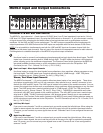
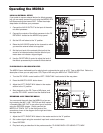
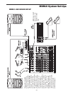
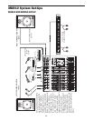
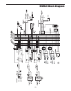
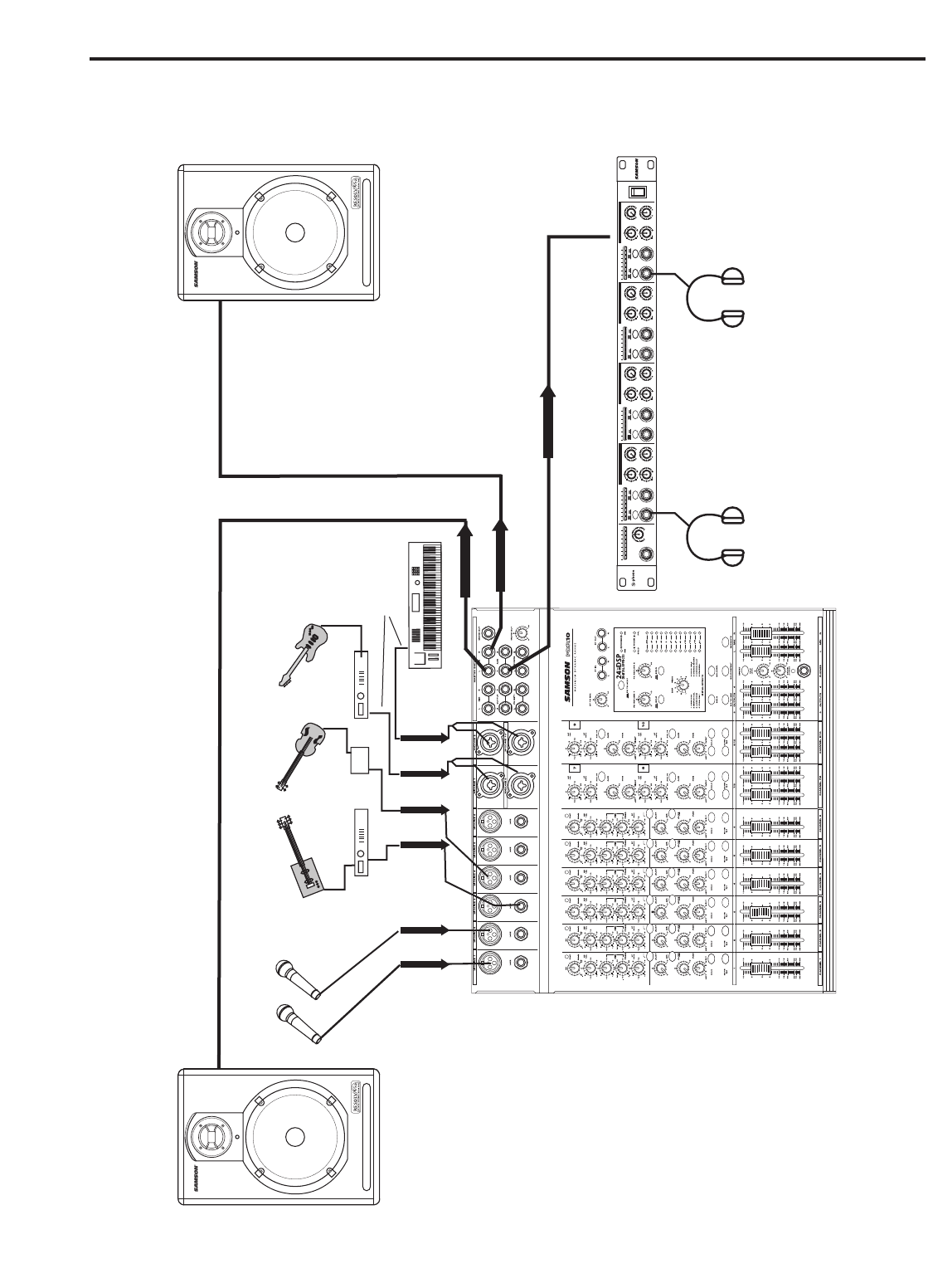
MDR10 System Set-Ups
This system shows the MDR10
in a recording set up with the
LEFT and RIGHT CONTROL
ROOM output hooked up to
powered studio monitors and
the AUX 1 feed headphone mix,
sent to a Samson S phone
headphone amp. For inputs,
two microphones are connect-
ed to channel 1 and 2’s low-
impedance inputs, and the
output of the Bass Direct Box is
also connected to the low-
impedance input on channel
4. The Keyboards, as well as
the Lead and Rhythm Guitar
signal processor's’ outputs, are
connected to the MDR10’s line
inputs.
MDR10 RECORDING SET-UP