


5
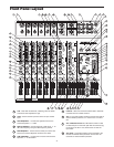
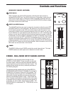
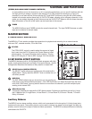
11 PAN – Controls the channel’s balance between left and right in
the stereo bus.
12 SOLO Switch (Input Channels) – Back-lit LED switch used to
assign the channel to the SOLO bus.
13 MUTE 3/4 – LED, back-lit switch used to Mute the input chan-
nel from the Main Left and Right mix bus, and at the same
time, assign the channel to the 3/4 output bus.
14 FADER – 60 mm audio taper fader provides smooth control
over level changes.
15 MIC INPUT – XLR input connector for the input channel’s Low-
Noise Microphone pre-amp.
16 LINE INPUT – 1/4-inch TRS ( TIP RING SLEEVE) input con-
nector for the input channel’s balanced Line level inputs.
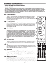
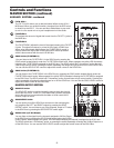
17 LOW FREQUENCY (Stereo Channels) - Controls the low band
of the Channel Equalizer, +/- 15 dB at 80Hz.
18 HIGH FREQUENCY (Stereo Channels) - Controls the high band
of the Channel Equalizer, +/- 15 dB at 12KHz.
19 AUX 1/2 Switch (Stereo Channels) - The auxiliary send on the
Dual/Mono channels can be set to either the AUX 1 or AUX 2
bus by using the back-lit, AUX1/2 switch.
20 MIC LINE – Combination Input connector for the Line or Low-
Noise Microphone Inputs on the stereo channels.
21 FX RET 1 (L/R Jacks) – Balanced inputs on 1/4-inch TRS con-
nectors for connecting external line level signal like those from
external effects processors.
22 3/4 OUTPUT – Balanced outputs on 1/4-inch TRS connectors
that carry the signals from the 3 and 4 mix bus.
23 MIX (L R Jacks) – Balanced outputs on 1/4-inch TRS connec-
tors that carry the signals from the Left and Right Main mix
bus.
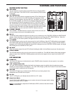
24 AUX 1 - 1/4-inch TRS output connector for Auxiliary 1.
25 CONTROL ROOM – Left and Right output connectors for con-
necting a monitor system.
26 AUX 2– Output connector for Auxiliary 2.
27 MONO OUT – The Left and Right main Mix outputs are
summed together to a monaural signal and sent out this con-
nector.
28 FX RETURN 2 (L R Jacks) – Balanced inputs on 1/4-inch TRS
connectors for connecting external line level signals like those
from external effects processors.
29 MONO OUT LEVEL – Used to set the volume of the MONO mix.
30 2 TK LEVEL - Control used to adjust the volume of the 2-track
input.
31 2 TRACK INPUTS – Connect a DAT, Cassette, Mini Disk or
Hard Disk Recording system.
32 FX TO AUX – When this switch is engaged, the FX RETURN
2 is sent to the AUX 1 output allowing the effects, external or
internal, to be heard in the monitor mix.
33 2 TRACK OUTPUTS – Connect a DAT, Cassette, Mini Disk or
Hard Disk Recording system.
34 PHANTOM – Indicates that the 48 Volt Phantom Power is on.
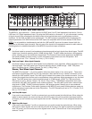
35 FX RETURN 2 Knob – Used to mix in level of the external
effects connected to the FX RETURN 2 inputs.
36 POWER – Indicates the MDR10 is powered up.
37 SOLO LED – Indicates SOLO is selected.
38 PFL LED – Indicates the SOLO is in PFL (Pre-Fader Level)
mode.
39 SOLO Switch (FX RETURN 2) – Back-lit LED switch used to
assign the FX RETURN 2 to the SOLO bus.
40 OUTPUT METER - Twelve segment display with VU ballistics
indicates main Mix level.
41 DSP PEAK LED - LED light illuminates when the signal sent to
the internal DSP is clipped.
42 SOLO/PFL Switch – Used to change the operating mode of
the SOLO bus from SOLO to PFL (Pre Fader Listen).
43 SOLO DEFEAT Switch – This global control back-lit, switch is
used to disconnect all channels from the SOLO bus.
44 MIX MUTE Switch – When the switch pressed, the red LED
lights indicating the Main Left and Right outputs are fully
attenuated.
45 MIX FADERS- Used to control the overall volume of the Left
and Right main Mix outputs.
46 HEADPHONE JACK – Connect stereo headphones here.
47 C ROOM/HEADPHONE – Adjusts the volume of the control
room speakers or headphones.
48 SOLO LEVEL – A rotary control knob used to set the overall
volume of the SOLO bus.
49 MIX/2TK– Switches between the main Mix and the 2 Track
in the Control Room output.
50 OUTPUT 3 & 4 FADERS – Used to control the overall volume
of the 3 and 4 mix outputs.
51 3/4 TO MIX Switch – When engaged, the LED lights and the
input channels which are a assigned to 3/4 will be mixed
together with the Main Left and Right Outputs.
52 SOLO Switch (3/4 Bus) – Back-lit LED switch used to assign
the 3/4 Bus to the SOLO bus.
53 DSP PRE-SET SELECT Knob – Used to switch between the 8
pre-sets of the internal DSP effects processor.
54 SOLO Switch (FX RETURN 1) – Back-lit LED switch used to
assign the FX RETURN 1 to the SOLO bus.
55 FX RETURN 1 – Used to mix in level of the external effects
connected to the FX RETURN 1 inputs.
Front Panel Layout