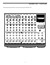
Guided Tour - Rear Panel
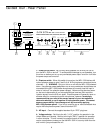
5: Main out (L, R) - These are the MPL 1502’s main outputs. You’ll usually use
these to connect the MPL 1502 to a power amp and speakers. The Main out
jacks are electronically balanced, so you should use balanced three-conductor
cabling and TRS plugs wherever possible (unbalanced two-conductor plugs can
also be inserted into these outputs, but you’ll get better signal quality and less
outside noise and hum if you use balanced lines). See the “Connecting the MPL
1502” section on page 10 for more information.
6: Aux Sends (1, 2) - These unbalanced 1/4” outputs allow you to route signal
from each of the two discrete Aux Sends to external devices such as effects
processors. Both Aux sends are post-fade and post-EQ. See the “Using the
Aux Sends and Returns” section on page 20 for more information.
7: Tape In/Out (L, R) - Use these two sets of dual RCA input jacks to connect
the inputs and outputs of a tape player to the MPL 1502. When the front panel
“Tape In / Channel 14/15” switch is pressed in, the input signal connected here
appears at stereo channel 14/15, at unity gain (during this operation, the channel
14/15 trim control has no effect). From there, it can be equalized if necessary
and routed to either or both Aux sends. The tape output signal is a duplicate of
the Main output, at unity gain. See the section in this manual entitled “Guided
Tour - MPL 1502 Main Section” (page 6) for more information.
8: Aux Returns (1, 2) - These unbalanced 1/4” inputs allow you to route signal
from external devices such as effects processors to either of the two stereo Aux
Returns. See the “Using the Aux Sends and Returns” section on page 20 for
more information.
9: Channel inserts (1 - 5) - Use these to insert an external effects processor
(such as outboard equalizer, compressor/limiter or noise gate) into any of the
MPL 1502’s five mono channels in an “effects loop” configuration. These jacks
accept 1/4” TRS plugs, with the ring carrying the send signal and the tip carrying
the return signal. Normally, this will be connected to a Y-cord; see the
“Connecting The MPL 1502” section on page 10 for more information and a
wiring diagram.
9


