


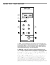
Connecting The MPL 1502 - General Suggestions
The actual connections you’ll make to and from the MPL 1502 will vary accord-
ing to the environment you use it in and the particular equipment you have.
In the “MPL 1502 Applications” sections at the rear of this manual, you’ll find
some suggested setups. Here are a few basic rules concerning MPL 1502
connections that will apply in most situations:
• In general, it’s best to make all connections with the MPL 1502 and any
connected power amplifiers turned off. If you must make connections with
the power on, make sure that the Main gain control is completely down (turn
the knob fully counterclockwise). Whenever powering down, turn the Main
gain control completely down and turn off the main power amps
first. Wait a
few seconds for their power supplies to discharge and then turn off all
connected equipment, turning the MPL 1502 off last.
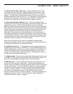
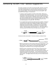
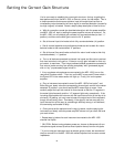
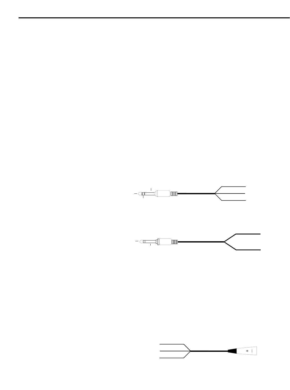
• Try to use balanced connectors and cabling wherever possible. These kind
of connections do a better job of rejecting extraneous noise and hum and
generally provide a cleaner signal. Although the MPL 1502 will accept
unbalanced connectors throughout, it specifically provides electronically
balanced inputs for all mono line inputs (channels 1 - 5) and for its main
outputs. The wiring diagram below shows how 1/4” TRS (Tip/Ring/Sleeve)
connectors should be wired for use with these inputs and outputs:
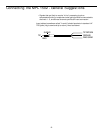
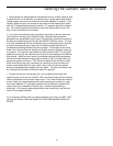
Unbalanced cables use standard 1/4” phone connectors, wired as follows:
• Make one connection at a time and then monitor the incoming signal. If you
hear a distinct hum or buzz, you may have a grounding problem with that
particular device. See the section in this manual entitled “Grounding
Techniques” for information on how to avoid grounding problems.
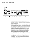
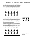
• NEVER connect a microphone and line level input to the same channel
simultaneously—use one or the other. You can have some channels
connected to microphones and others to line level signals (for example, you
might want to plug mics into channels 1 - 3 and line level signals into the
remaining channels)—just don’t have both kinds of inputs connected to the
same channel. The diagram below shows how your mic connectors should
be wired:
10
TIP +
GROUND
RING -
RING
TIP
SLEEVE
+ SIGNAL
GROUND
+ SIGNAL
GROUND
3 - SIGNAL
1 GROUND
2 + SIGNAL
TO MIXER