


Owner's Manual
7
XML POWERED MIXERS
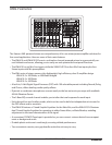
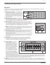
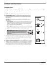
Input Channel Section
The following section details each part of the XML’s INPUT CHANNELS including the 3-BAND EQ, the MONITOR and EFX
sends, GAIN and VOLUME controls.
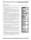
Controls and Functions
1. Peak - This LED indicator will ash RED when the channel input signal peaks.
To reduce distortion, turn the VOL control counterclockwise until the clip
indicator does not light during normal use.
2. Equalizer (HF, MF, and LF) - This three-band equalizer allows you to contour
a channel’s high, mid, and low frequency bands. When the control is set to
the 12 o'clock (detent) position, there is no eect on the signal. Turning the
controls fully clockwise will raise the level of the frequency band +15 dB,
while turning the controls fully counterclockwise will lower the level of the
frequency band -15 dB.
3. AUX 1/MON - The AUX 1 controls the amount of signal sent to the Monitor
bus. The AUX 1 send is pre-fader so the signal is unaffected by the position
of the VOL control. These sends are usually used to create a separate mix for
a monitor system. The Monitor bus signal is routed to the front panel MONI-
TOR jack, and may be routed to the SPEAKER RIGHT/MONITOR output jacks,
depending on the setting of the MODE switch. When the MON send knob is at
the 12 o’clock center position, the signal is routed with unity.
4. AUX 2/EFX - The AUX2/EFX send knob allows you to route the signal to the
internal digital eects processor and the EFX 2 SEND output. The AUX2/EFX
send is post-fader so the level of the signal is determined by the position
of the channel Volume control. When the AUX2/EFX send knob is at the 12
o’clock position, the signal is routed with unity.
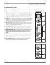
5. VOL - This knob controls the volume of channel inputs and is used to continu-
ously adjust the loudness of the various signals being blended together at
the Main Outputs. Moving the knob counterclockwise causes the signal to be
attenuated. Conversely, when rotated clockwise, the signal is boosted.
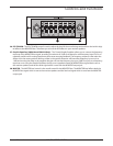
NOTE: For best signal-to-noise ratio, all VOL controls for channels carrying
signal should generally be kept at or near the 12 o’clock (unity) position.
Channels that are unused should have their Volume controls kept fully coun-
terclockwise at their minimum level.
6. COMP (XML610 and XML910 only) - The COMP knob adjusts the level of
compression applied to the channel. As the COMP knob is turned clockwise,
the compression ratio is raised and the output gain is adjusted accordingly.
The dynamic range of the channel is narrowed, where softer signals will
be magnied and loud signals will be subdued to sit better in the mix. You
should use your ears when adding compression to a signal. Too much com-
pression can create a pumping eect, eliminate all dynamic range, and lead to
feedback.
7. PAD 20 dB switch, Channels 1 to 4 (XML610 and XML910 only) – Use this
switch to match the type of input signal you are supplying. If the PEAK light
of an input continues to light even when the VOL is turned down, depress the
PAD switch . Always turn the VOL completely counterclockwise before press-
ing the PAD switch to avoid damaging your speakers.
2
1
3
4
5
6
7
8
9