


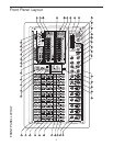

Front Panel Layout
5
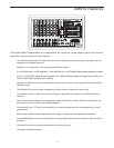
FRONT PANEL
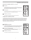
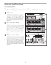
1 AUX 1 MONITOR – Controls the amount of signal sent
to the monitor amp and AUX 1 send jack.
2 AUX 2/EFX – Controls the amount of signal sent to the
digital effects processor and AUX 2 send jack.
3 HIGH FREQUENCY – Controls the amount of treble
applied to that channel.
4 MID FREQUENCY – Controls the amount of midrange
applied to that channel.
5 LOW FREQUENCY – Controls the amount of bass
applied to that channel.
6 PAN (Balance on stereo channels) – Adjusts the
amount of signal sent to the Left or Right bus.
7 PEAK LED – Indicates that the signal is peaking
or overloading.
8 GAIN – Sets the overall level for the Mic or Line
input.
9 VOLUME – Controls the overall volume of that chan-
nel.
10 LINE INPUT – Balanced input for line level sig
nals.
11 MIC INPUT – Input connector for low impedance bal-
anced microphone input.
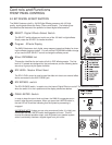
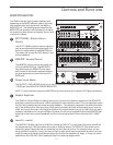
12 EFX LEVEL – Master control for the amount of signal
sent to the DSP and AUX 2 Send.
13 EFX BYPASS – Shuts off the internal DSP.
14 SELECT – Selects one of the 100 digital effects pre-
sets available.
15 EFX PROGRAM DISPLAY – Show the current DSP
effect pre-set.
16 MAIN LED METERS – Indicates the amount of output
signal on the main stereo output.
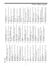
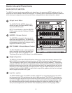
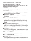
32 DJ CROSSFADER – Used to mix between the
CD1 and CD2 inputs.
33 REC OUT – Output used to send main mix to an
external recorder.
34 CD2 INPUT – Used to connect input from a
CD/MD/Tape Deck.
35 CD2 INPUT VOLUME – Controls the amount of
volume from an external line source like CD,
MP3 or Tape.
36 CD1 INPUT – Used to connect input from a
CD/MD/Tape Deck.
37 CD1 INPUT VOLUME – Controls the amount of
volume from an external line source like CD,
MP3 or Tape.
38 AUX 1 SEND – Monitor signal output connector.
39 MIX OUT – Left and Right output jacks for the
main mix output pre amp signal.
40 AMP IN – Left and Right input jacks for connect-
ing directly to the internal power amplifier.
41 EFX FOOTSWITCH – Switches the effects on or
off.
42 AUX 2 SEND – Effects output jack for connecting
an external effects processor.
43 EFX RETURN – Left and Right input connectors
for mixing external signals.
44 PEAK LIMTER SWITCH – Use to engage the inter-
nal Peak Limiter.
45 LINE / MIC INPUT (Stereo Channels) –
Combination connector with 1/4-inch TRS (TIP
RING SLEEVE) input to the right line input, plus
XLR mic input.
45 LINE L INPUT (Stereo Channels) – 1/4-inch TRS
(TIP RING SLEEVE) input to the left line input.
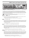
17 MONITOR LED METER – Indicates the amount of
output signal on the monitor output.
18 CLIP LEDS – Indicates power amp maximum level.
19 AMP 1 and AMP 2 PROTECT LEDs – Indicates
power amp is in overload and that the protect cir-
cuit is active.
20 PHANTOM POWER – Provides 48 volts to the XLR
inputs for powering condenser microphones.
21 MUTE CH 1 - 6 SWITCH – Used to turn off the inputs
of channel 1 through 6.
22 MODE SWITCH – Configures the output of the
power amps. Stereo or Main/Monitor 450W X 2 (4
ohms), Main Bridged 600W X 1 (8 ohms).
23 POWER LED – Indicates status of the power switch
On/Off.
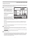
24 MONITOR GRAPHIC EQ – Provides dual 10-Band
equalization for the channel monitor.
25 EFX TO MON – Effects return control for monitor
channel.
26 MASTER (MONITOR) – Master volume control for
monitor amp and AUX 1 Send.
27 LOW CUT (MONITOR) – Used to attenuate the low
frequencies below 75 Hz on the monitor output.
28 EFX RETURN (MAIN) – Effects return control for
main channel.
29 MASTER – Master volume control for main
stereo/mono amp and main mix out L/R.
30 MAIN GRAPHIC EQ – Provides dual 10-Band
equalization for the channel monitor.
31 LOW CUT (MAIN) – Used to attenuate the low fre-
quencies below 75 Hz on the main output.