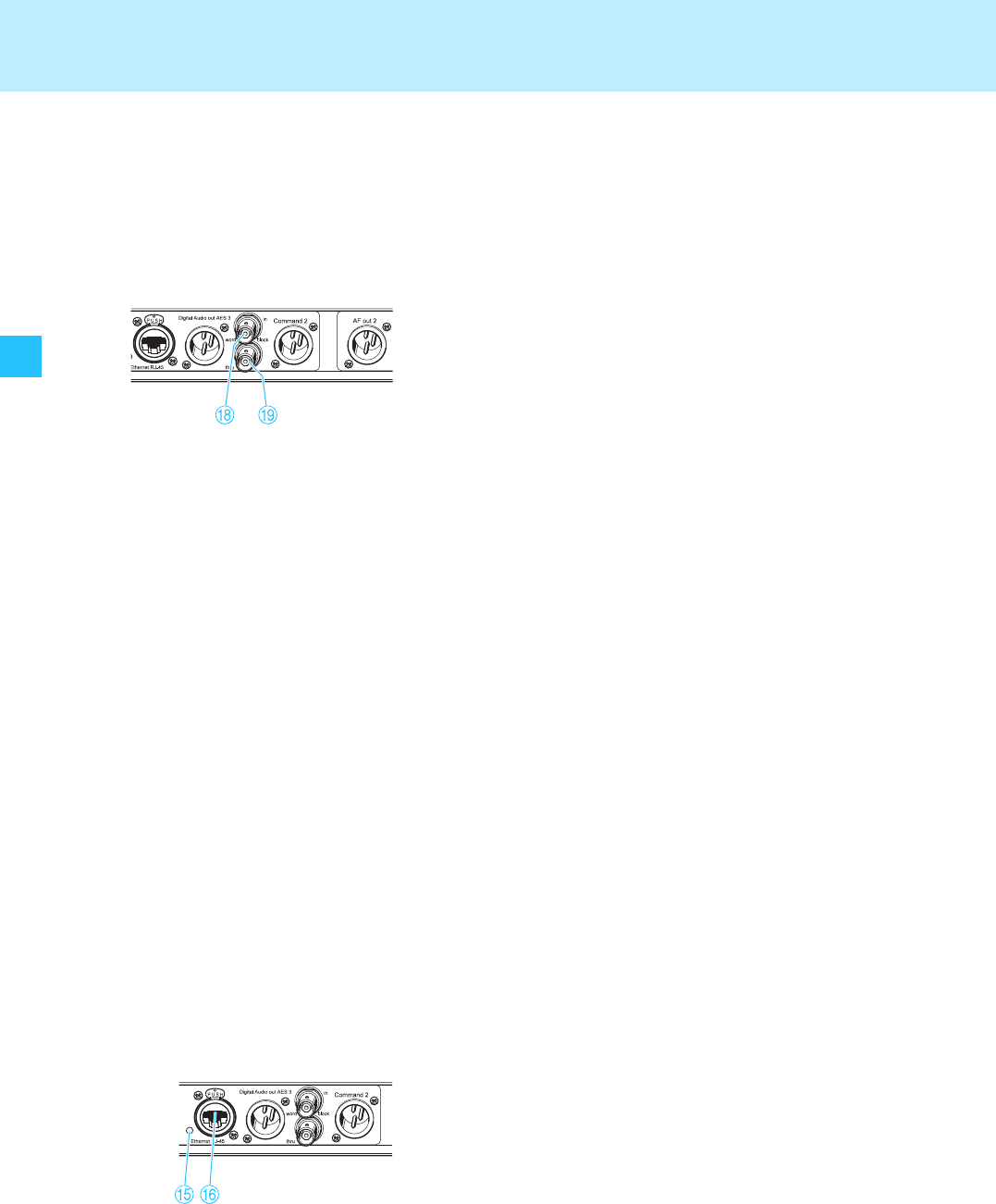
18
Putting the receiver into operation
Connecting an external word clock generator
The receiver can digitalize the audio signal and output it via the digital
balanced XLR-3M audio output
G. The built-in A/D converter supports
sampling rates of 44.1 kHz, 48 kHz, 88.2 kHz and 96 kHz.
If you want to connect an external word clock generator instead, proceed
as follows:
̈ Use a shielded 75 Ω coaxial BNC cable to connect the external word
clock generator to the BNC socket
H.
̈ Select “Ext.” in the “Clock” menu (see “Selecting the sampling rate for
digitalization” on page 31).
The display for external word clock synchronization
B:
– lights up permanently when the digital audio output of the receiver
is synchronized with the external word clock generator,
– flashes when “Ext.” is selected in the “Clock” menu but no external
word clock generator is connected,
– flashes when the signal of the external word clock generator is
available but has not synchronized the digital audio output of the
receiver
– is off when the receiver’s internal word clock generator is used.
Notes:
– Both receivers of a twin receiver use the same word clock signal.
– The receiver has a BNC socket for word clock daisy chain output
I for
supplying the word clock signal to further daisy chained receivers
using the supplied BNC word clock daisy chain cable. The word clock
signal is also daisy chained when a receiver is switched off.
Connecting the receivers to a PC via Ethernet
The receivers can be centrally configured and monitored via a PC and the
supplied “Wireless Systems Manager” software. Additionally, you can
update the firmware in the receivers.
To connect the receivers to a PC:
Note:
If you want to connect several receivers to the same Ethernet socket of
your network, you require a standard 100Base-T Ethernet switch.
̈ Connect the supplied RJ 45 Ethernet cable to the RJ 45 socket for LAN
connection
F and to your switch or network.
̈ Install the “Wireless Systems Manager” software on your PC.
̈ Continue as described in the instruction manual of the “Wireless
Systems Manager” software.
The LED for LAN data transmission
E lights up when data is
transmitted.


