


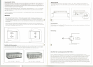
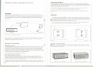
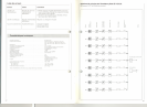
Mains supply
Ex works the chassis is prepared lor operation at 220 VI 50 - 60 Hz. For operation at 110 V mains
two additional wire bridges have to be solde red in (see lig. 6
+ 7).
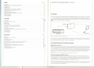
AF-connection
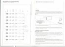
The AF-inputs are balanced and designed lor signal levels 0160 mV - 3 V.
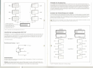
Connection of power radiator SZI1 019 A
The modulated RF-signal with a level 012 Vpp (source impedance 60 Q) is available at RF-output
sockets @ and @. They are decoupled lram each other and connected in parallel. The connec-
tion to the radiator is to be done with 50 Q-coaxial cable. For that Sennheiser offers the lollowing
cables: AV 20 (20 m), GZL 1019 A 10 (10m). GZL 1019 A 5 (5 m) and GZL 1019 A 1 (1 m). The si-
gnal is looped Irom the lirst radiator to the second, lram the second to the third etc. (see user's
guide SZI1 019 A). Max. 100 radiators may be connected in senes. The max. cable length between
the transmitter and the last radiator shouldn't exceed 1500 m. II the cable length ISmore than 300 m
the output 01the last radiator has to be terminated with 50 Q in order to prevent standing waves.
12
'~-t~,~11 I I 11I , , , , \1ijr~"
2~ ~4
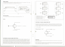
Fig.6
Wiring
'1
5-pin screwable
3
3
'r
f
2
)}
Fig.7
3
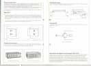
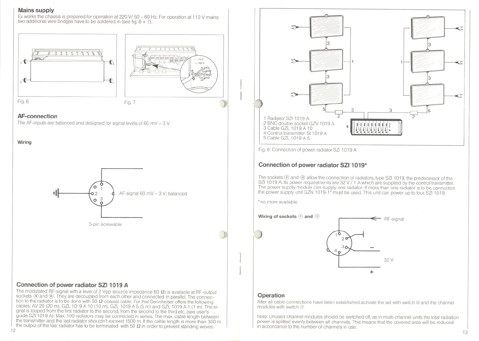
1 Radiator SZI1 019 A
2 BNC double socket GZV 1019 A
3 Cable GZL 1019 A 10
4 Control transmitter SI 1019 A
5 Cable GZL 1019 A 5
Fig. 8: Connection 01 power radiator SZI1 019 A
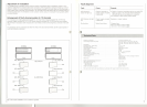
Connection of power radiator SZI1 019*
AF-signal 60 mV - 3 V; balanced
The sockets (ii) and @ allow the connection 01radiators,type SZI1 019, the predecessor 01the
SZI1 019 A. Its power requirements are 32 V 11 A whlch are supplied by the contra I transmitter.
The power supply module can supply one radiator. II more than one radiator ISto be connected
the power supply unlt GZN 1019-1 * must be used. Thls unit can power up to lour SZI1 019.
* no more available
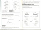
Wiring of sockets
(ii) and @
RF-signal
)
I
I
32 V
+
Operation
After all cable connections have been established actlvate the set with switch @ and the channel
modules with switch CD.
Note: Unused channel modules should be sWltched off, as in multi-channel units the total radiation
power is splitted evenly between all channels. This means that the covered area will be reduced
in accordance to the number 01 channels in use.
13
I