Adjustment of modulation
For adjusting the modulation each chan ne I module is equipped with a sensitivity control @.The
optimum adjustment is reached when the red LED-s of the modulation indicator @)light up at level
peaks. If, inspite of correct adjustment, the input signal exceeds its normal value for short periods, a
high quality limiter prevents overmodulation. Up to 30 dB overmodulation will be controlled without
increasing distortion. The limitation is even useful in some cases, for example if facing widely differ-
ing sound levels.
Enlargement of the 9-channel-system to 12 channels
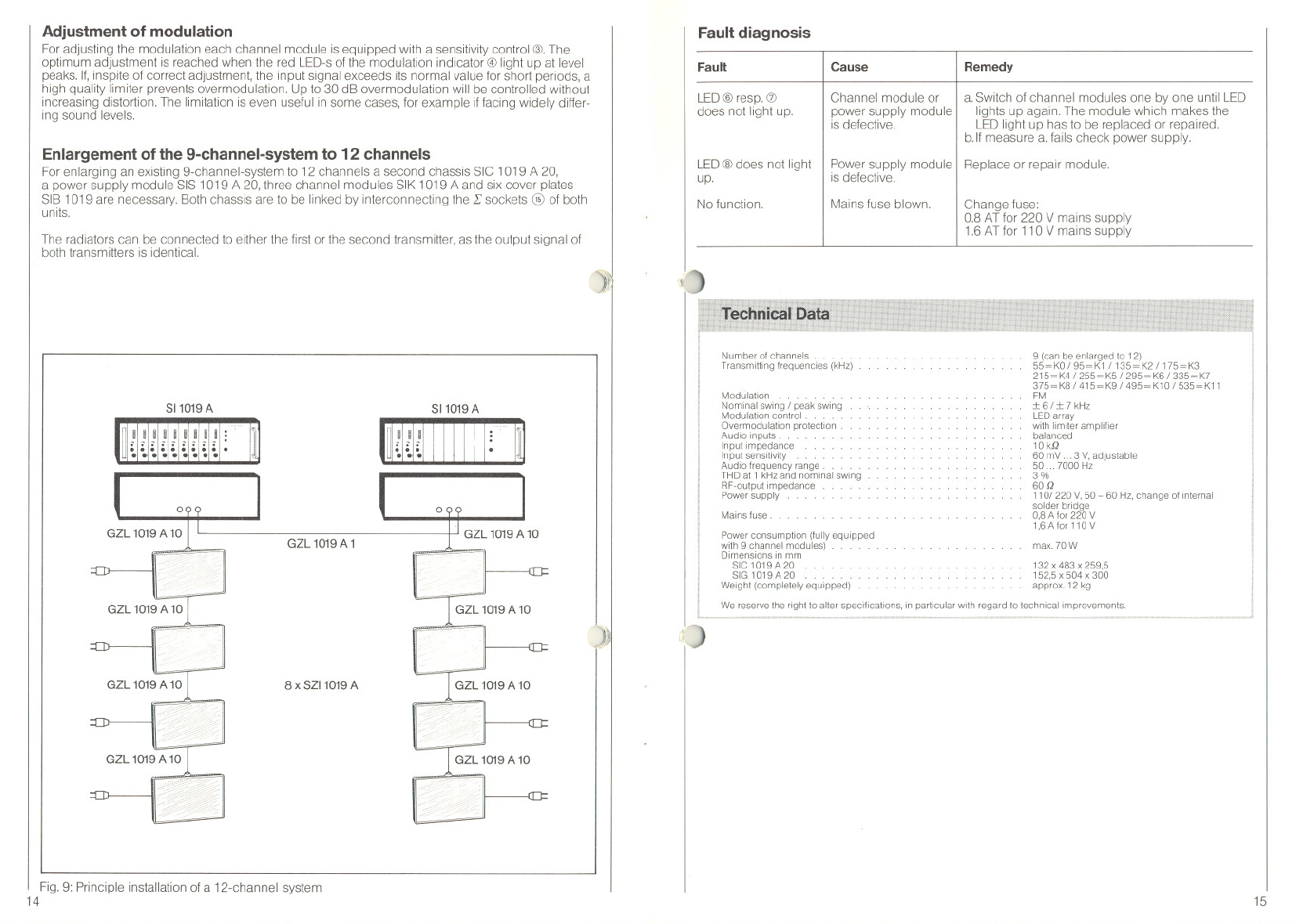
For enlarging an existing 9-channel-system to 12 channels a second chassis SIC 1019 A 20,
apower supply module SIS 1019 A 20, three channel modules SIK 1019 A and six cover plates
SIB 1019 are necessary. Both chassis are to be linked by interconnecting the L sockets @ of both
units.
The radiators can be connected to elther the first or the second transmitter, as the output signal of
both transmitters is identical.
811019A
811019A
~
~
0
GZL 1019 A 1
GZL 1019 A 10
8 x 8Z11019 A
Fig. 9: Principle installation of a 12-channel system
14
)1
Fault diagnosis
Fault
Cause
Remedy
LED @ resp. CD
does not light up.
Channel module or
I
a. Switch of chan ne I modules one by one until LED
power supply module lights up again. The module which makes the
is defective. LED light up has to be replaced or repaired.
b.lf measure a. fails check power supply.
PowersupplymoduleI Replaceorrepairmodule.
IS defective.
LED @does not light
up.
No function.
Mains fuse blown.
Change fuse:
0.8 AT for 220 V mains supply
1.6 ATfor 11O V mains supply
'[~
Number of channels .
Transmlftmg frequencies (kHz)
9 (can be enlarged fo 12)
55=KO / 95=K1 /135= K2 / 175=K3
215=K4 / 255= K5 / 295= K6 / 335=K7
375=K8 / 415= K9 / 495= K10 / 535=K11
FM
:1:6/:1:7 kHz
LEDarray
with Ilmiter ampllfler
balanced
10 kQ
60 mV ...3 v, adfustable
50...7000 Hz
3%
60 Q
110/220v. 50- 60 Hz, change of internal
solder bridge
0,8 A tor 220 V
1,6 Afor 110 V
Modulation. . . .
Nominal swing / peak swing
Modulation control . ..
Overmodulation protectlon .
Audlo inputs.
Input Impedance
Input sensltivity . .
Audio frequency range. . . . .
THD at 1 kHzand nominal SWing
RF-output impedance
Power supply
Mains fuse .
Power consumption (fully equlpped
with 9 channel modules)
Dimensions in mm
SIC 1019A20
SIG 1019 A 20 . . . . . .
Weight (completely equipped)
max. 70 W
132 x 483 x 259,5
152,5 x 504 x 300
approx. 12 kg
We reserve the right to alter speciflcatlons, in particular with regard to technical improvements.
i;'~
15
1111 I 11
l:
J
.......
........


