


2
MICROPHONE PLACEMENT
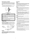
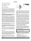
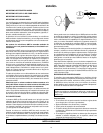
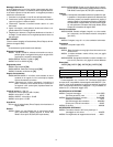
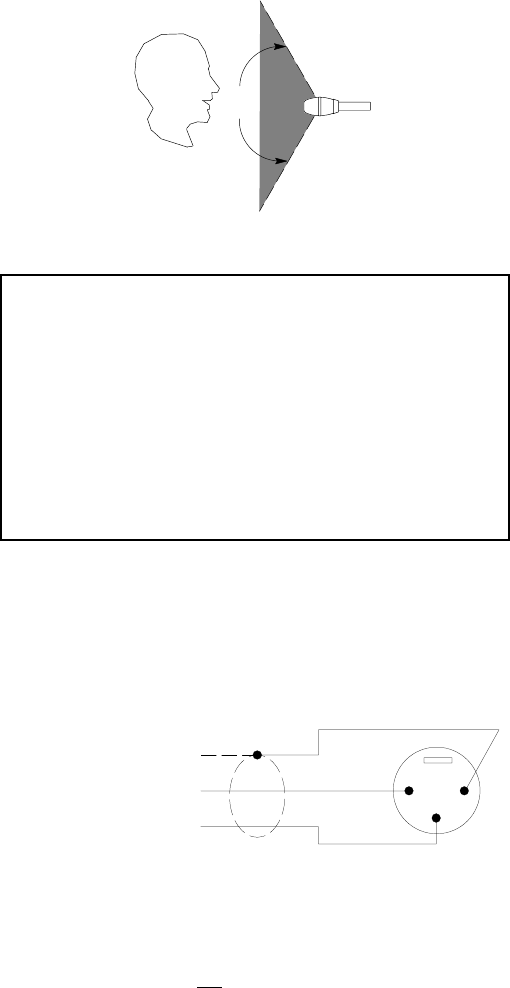
Use one AMS microphone to cover one or two talkers. To acti-
vate the microphone, a talker must be within the 120_
acceptance
angle (See Figure 2). The talker must also be at least 9 dB louder
than any other sound source outside of the 120_ acceptance
angle.
• The closer the microphones are to the talkers, the louder the
sound system can be before feedback occurs.
• Always use the fewest number of microphones necessary.
120
o
ACCEPTANCE ANGLE
Figure 2
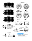
IMPORTANT
Place the microphone at least 1 meter (3 ft) from the wall be-
hind it, and at least 0.3 meters (1 ft) in front of any bulky objects.
AMS24 and AMS26: The grille must be at least 203 mm (8 in.)
above any horizontal surface. If necessary, you can raise the
AMS26 an additional 76mm (3 in.) using the optional Model
A26X Desk Stand Extension.
AMS28: The microphone must be kept at least 76 mm (3 in.)
away from any solid surface. This includes table tops, lecterns,
and other hard edges that the user may lean into and note-
books they may be holding while talking.
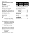
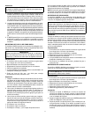
CONNECTIONS
AMS microphones use standard two conductor shielded micro-
phone cable. For most applications, cable lengths of 150 meters
(500 ft) or more are acceptable.
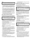
NOTE: The shield must be connected to pin 1 at both ends
of the cable. Ground all cables to the AMS mixer chassis.
SHIELD
RED
BLACK
G
1
2
3
Red = pin 2
Black = pin 3
Shield = pin 1
(and ground lug)
CABLE WIRING DIAGRAM
Figure 3
POWER
AMS microphones do not use standard phantom power. Only
use the 7 Vdc bias power provided by and AMS mixer.
Connect-
ing the microphone to any other mixer or power source may
damage the microphone.
MOUNTING
AMS22
To permanently mount the AMS22 to a table, desk or lectern,
drill a hole through the surface, then insert a 4-40 screw through
it and into the threaded nut in the microphone base.
Note: Use the largest flat surface possible. If the mounting sur-
face is too small, low-frequency rolloff may occur and the micro-
phone may pick up more background noise.
AMS24
1. After optimum locations are determined, drill the surface for the
cable. The cable diameter is approximately 2.5 mm (0.1 in.).
2. Mount the flange, drilling pilot holes for the mounting screws,
using the flange as a template.
3. With the flange mounted, thread the cable through the hole.
4. Screw the microphone gooseneck to the flange.
Note:
• If more cable length is needed, use high-quality, shielded
two-conductor microphone cable similar to that supplied with
the AMS24.
Make sure proper polarity is maintained.
• An optional accessory (A24QG) is available to convert the
AMS24 gooseneck microphone to a direct plug-in microphone
with a three-pin male XLR connector.
AMS26
Use the supplied A57F swivel adapter to install the AMS26 onto
a microphone stand or gooseneck.
AMS28
1. While holding the AMS28 by the rubber ring of the lavalier as-
sembly, place the lavalier cord around the user’s neck and se-
cure the free end of the cord in the slot at the side of the assem-
bly.
2. Adjust the cord length so that the AMS28 is 200 to 250 mm
(8 to 10 in.) below the user’s mouth.
3. Fasten the clip to the user’s clothing and pull the cord through
the slot to take up slack. If desired, the clip can be rotated for
left or right fastening, or it can be removed by turning it to the
vertical position and pulling straight out.
Alternate method:
In certain situations, the cord may slip through the open slot at
the side of the lavalier. If necessary, use the following method:
1. Tie a knot in the cord about 25 mm (1 in.) from the free end.
2. Place the rubber ring over the microphone, taking care not to
cover the grille or any side slot.
3. Place the microphone–lavalier assembly around the talker’s
neck.
4. Open the spring–loaded alligator cip at the back of the lavalier
and slip the cord through the open clip.
5. Adjust for proper length and release the clip. The knot will stop
the cord from pulling through the closed clip.