


Copyright 1992, Shure Brothers Inc.
27A8319 (LG)
Printed in U.S.A.
U.S. Patent 4,658,425; other patents pending
0
1
2
3
4
5
6
7
8
9
100
1
2
3
4
5
6
7
8
9
100
1
2
3
4
5
6
7
8
9
10
432
LINK
1
2
3
4
5
6
7 8 9
10 11
12
13
14
15
16
17
18
19
FP410
MODEL
FP410E
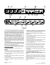
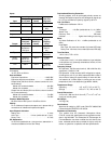
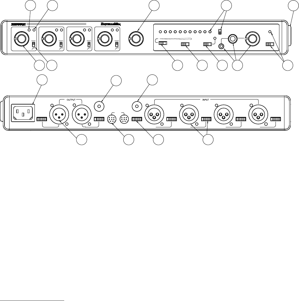
FIGURE 1
TAPE OUT
MIC LINE MIC LINE MIC LINE MIC LINE MIC LINE MIC LINEPHANTOM
OFF ON
OUT IN
MASTER
PULL FOR 1 KHZ TONE
BATTERY TEST MANUAL AUDIO LIMITER IN
PULL FOR MONITOR
OFF ON
PEAK
VU
100%
MONITOR IN
4321
PHONES
1
0
1
2
3
4
5
6
7
8
9
10
0
1
2
3
4
5
6
7
8
9
10
–20 –10 –7 –5 –3 –2 –1 0 +1 +2 +3
–24–20 –16 –12 –8 –4 0 +4 +8 +12 +16
The
FP410E has numerous applications in video production
and
audio
recording, broadcasting, and sound reinforcement.
In
any speech
pickup application where multiple microphones
are
required, the FP410E dramatically
improves audio quality
.
Switching
from manual to automatic operation
allows an indi
-
vidual talker’s voice to rise above the background noise and
reverberation
to become clearer and more intelligible.
Each
FP410E handles up to four microphones or line–level
signals. Any high quality, low–impedance, balanced micro-
phone using a dynamic or condenser* transducer (including
wireless
and shotgun types) can be used. Additional FP410E
mixers
can be interconnected using the rear–panel link
jacks.
Complete
manual operation is also available using a
front–pa
-
nel selector switch..
The
FP410E is supplied with optional bumpers (feet) for use
on horizontal surfaces, a short cable for linking two FP410E
mixers, and a rack–mounting kit for installation in a standard
483
mm (19–inch) audio equipment rack..
The FP410E is supplied for 230 Vac operation (line fuse
0.05
A) and its line cord is terminated by a Schuko ac plug.
*Self–powered
or operable on 14 or 48 Vdc phantom power
.
Features
•
Reliable, quick–acting, noise–free microphone selection––
automatically
adjusts to changes in background room noise
• Front–panel
channel gain and master controls operate as
in
conventional mixers
• Selectable hold time keeps microphones on during short
pauses
in speech
•
Selectable Of
f–Attenuation control for seamless operation
• Automatic gain adjustment as additional microphones are
activated
• Defeatable
“Last Mic Lock–On” circuit keeps at least one mi
-
crophone
on at all times—maintains
acoustic ambiance and
prevents
confusing background sound changes
• Wide, flat frequency response and low distortion up +18
dBm
output
• Linking capability for systems containing over 25 mixers
and
over 100 microphones
• LED indication of microphone channel mix levels, output
level,
and limiter action
• Automatic muting prevents annoying thumps and loud-
speaker
damage when unit is turned on and of
f
• Transformer–balanced inputs and outputs switchable to
line–
or microphone–level
•
Separate monitor input and tape output (aux–level) jacks
•
Front–panel headphone monitor jacks with level control
•
Front–panel auto–disable switch for manual operation
•
Operates from ac mains voltage or two 9 V batteries
• Switchable 14 V or 48 V phantom powering for condenser
microphones
• VDE
Approved
for safety under DIN VDE 0860/05.89, har
-
monized with CENELEC HD 195 S6.
CONTROLS,
CONNECT
ORS, INDICA
T
ORS
(See
Fig
-
ure 1)
1.
Microphone Channel Gain Controls
1–4
: At “0” position, mi
-
crophone
channel is removed from operation. T
urning control
clockwise activates microphone channel and allows adjust-
ment
of microphone level.
2.
Input Normal Green LED: Should flicker with normal speech
levels.