


2
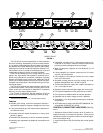
3. Input High Red LED: Should flicker only on loud speech
peaks.
4.
Flat (
—
)/Low–Cut (
/
) Slide Switches: Provide
low–frequen
-
cy rollof
f to reduce undesirable low–frequency signals such as
wind
noise.
5.
MASTER
Rotary Control: Determines
the level of the com
-
bined input signals at Mic/Line, Tape and Phones outputs.
PULL
FOR 1 kHz T
ONE position activates 1 kHz tone oscilla
-
tor
(tone level is determined by Master control setting). Oscilla
-
tor
signal appears at all outputs. When oscillator is not in use,
knob
should be pushed in.
6.
PEAK/VU
Output Level Meter: Meter function
is selected by
adjacent
PEAK/VU slide switch. In PEAK switch position, me
-
ter indicates peak signal levels. In VU position, it indicates av
-
erage
signal levels, simulating a true VU meter
.
7.
BATTERY
TEST
Momentary Slide Switch: Operates in
con
-
junction with PEAK/VU Meter to indicate battery condi-
tion.With
POWER switch on and switch
in momentary–on po
-
sition, new set of batteries lights all green LEDs. Number of
green LEDs lit indicates approximate battery life remaining
when
alkaline batteries are used. N
OTE:
POWER LED
begins
flashing
when total battery supply voltage drops to 10 Vdc (one
green
LED lit).
8.
MANUAL/AUTO
Slide Switch: Selects manual or automatic
microphone
operating mode. In MANUAL
position, unit oper
-
ates as a conventional microphone mixer. In AUTO position,
unused
microphones automatically turn of
f.
9.
LIMITER IN
Slide Switch: Activates fast–acting, peak–res
-
ponding limiter circuit to cut overload distortion during loud
program intervals without affecting normal program levels.
The
red limiter LED indicates limiting action.
10.
PHONES
1
/
4
–inch and 3.5
mm Phone Jacks: Permit moni
-
toring mixer output through most stereo or mono headphones.
PULL FOR MONITOR switch applies signal from rear–panel
MON IN 3.5 mm phone jack to headphones amplifier. When
switch is activated, mixer output signal does not appear in
headphones output. PHONES rotary control determines
headphone
level in either case.
11.
POWER
Slide Switch: Applies ac
or battery power to mixer
circuitry.
Adjacent green LED indicates
power–on status and,
in
battery operation, flashes when total
battery voltage drops
to 10 Vdc..
12.
230 V
AC, 50/60 Hz 8W
3–Pin Power Connector: For con
-
nection
to 230 V
ac, 50/60 Hz power outlets.
13.
OUTPUT
3–Pin Male XLR Connectors: For connection to
one
or two amplifiers, recorders or other mixers. Output
signal
levels are individually switchable to Line level or low–impe-
dance Mic level by adjacent individual MIC/LINE slide
switches.
Both
jacks provide the same signal information but
are electrically isolated.
14.
T
APE OUT
3.5 mm Phone Jack: Provides output signal to
feed
unbalanced aux–level inputs of most tape recorders and
amplifiers.
15. LINK IN/OUT 8–Pin miniature DIN Jacks: Using link
cables, these jacks permit virtually unlimited number of
FP410E mixers to be stacked to achieve additional input ca-
pacity.
Jacks carry
audio signals, MaxBus and Last Mic Lock–
On
information.
16.
MON IN
3.5 mm Phone Jack: Sends external Aux or Line–
level
source to headphones amplifier without interrupting other
mixer
functions. Jack is
activated by pulling front–panel PULL
FOR MONIT
OR knob outward.
17.
PHANT
OM ON/OFF
Slide Switch: Controls application of
14 Vdc phantom power for condenser microphones to all in-
puts.
With
switch on and INPUT MIC/LINE switches in MIC po
-
sition,
+14 Vdc is applied to pins 2 and 3 of each input XLR con
-
nector.
NOTE: Phantom power can be internally set
to 48 Vdc
(see
Modifiable Functions
section). When using other than
Shure
condenser microphones, verify that voltage and source
resistance
requirements are compatible (see
Specifications)
.
18. INPUT 1–4 Female 3–Pin XLR Connectors: Permit con-
nection
to balanced, low–impedance microphones or line–le
-
vel
sources. Adjacent MIC/LINE
slide switches adjust inputs to
match source levels.
19.
Battery Compartment: Accepts two 9–volt
batteries for re
-
mote
operation or as automatic backup in the event of ac pow
-
er
failure.
PLEASE
NOTE
This product is not completely disconnected from the mains
supply
when the power switch is Of
f.
INSTALLATION
AND OPERA
TION
Mixer Installation
Install
the FP410E as follows.
If the unit is to be placed on a
horizontal
surface, attach the four supplied bumpers to the cor
-
ners
of the chassis bottom to prevent marring the surface.
If
the FP410E is to be rack–mounted in a standard 483
mm
(19–inch)
audio equipment rack, remove the
two Phillips head
screws
from each FP410E
side panel, place the rack “ears” in
position at the sides (rack–mount holes facing forward), and
secure the ears with the previously removed Phillips head
screws.
NOTE: The rack ears are asymmetrical; the
wider
ear
should
be
on your right (as you face the front panel) to permit
access
to the battery
compartment while the FP410E is in the
audio
equipment rack. Install the rack–mounted FP410E in the
equipment rack and secure it with the four supplied rack–
mount screws.
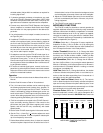
Make electrical connections as follows.
1. For battery operation, compress
the release latches of the
battery
drawer with thumb
and forefinger
, and withdraw the
drawer from the compartment. Observing battery polarity
markings, insert two fresh 9–volt batteries in the drawer
slots.
With the Power switch on, slide the Battery T
est
switch
to the right to determine battery condition. IMPORTANT:
Battery operating life is reduced when microphones are
phantom–powered—especially
by 48 Vdc phantom
power
-
ing. For ac operation, connect the power cord to a 230 V
ac,
50/60 Hz source.
2. Connect the
microphones and/or line–level signal sources
to
the Mic Input connectors
(use conventional 2–conductor