


4
condenser microphones to be used are compatible with the
selected
voltage. If the microphones can operate properly with
14
V phantom power
, that position should be used to avoid ex
-
cessive
battery drain.
INTERNAL MODIFIABLE FUNCTIONS
WARNING
Voltages
in this equipment are hazardous to
life. No user–
serviceable parts inside. Refer all servicing to qualified
service
personnel.
In addition to the user–modifiable functions described
above, the FP410E is designed so that many of its functions
can
be modified by a qualified technician. Instructions on
im
-
plementing these modifications are provided in the FP410E
Service
Manual
which is obtainable from Shure. These modifi
-
cations
are:
1. Change Monitor In sensitivity
.
2. Change T
ape Out level.
3. Change Of
f–Attenuation value.
4. Change low–cut filter frequency
.
5. Change Peak meter attack and decay time constants.
6.
Change 0 VU Meter calibration to level other than +4 or +8
dBm.
7.
Change
Limiter threshold beyond the positions permitted by
Switches
2 and 3 (see Figure 2).
8.
Change to permanently lock one or more microphones
on.
9. Change to permanently prevent one or more microphone
channels
from activating.
10. Change the preset Hold T
ime values.
11. Change the Monitor In jack to an Aux In jack function for
cascading
mixers or creating a “mix–minus”.
12. Change to provide reduced–level program feed in head-
phones
when Pull For Monitor switch is activated.
WARNING
The safety certifications of the FP410E do not apply if the
operating
voltage is changed from the factory setting.
ADDITIONAL INFORMATION
Limiter
The
front–panel Limiter switch
turns on a fast–acting, peak–
responding limiter circuit that cuts overload distortion during
loud program intervals without affecting normal program lev-
els. When the switch is In (operating), the FP410E output is
limited
to
approximately +16 dBm. Increasing the individual or
Master
gain controls will increase the average output and
the
amount
of limiting. The limiter threshold can be changed from
its factory setting as described in the
Modifiable Functions
section. The front–panel red LED adjacent to the Limiter
switch
indicates limiter action.
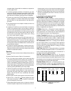
Linked
Mixers
The
FP410E provides four microphone
inputs. If additional
mic
inputs are needed, more
FP410Es (over 25, if necessary)
can
be “linked” using link cables of the type supplied. A
setup
like this can provide over 100 mic inputs. As long as the link
jacks of all mixers are connected (out–to–in, sequentially,
leaving one Link In and one Link Out jack unconnected), the
automatic
mixing functions will be shared by all units.
When FP410E mixers are linked,
Shure Intellimix
control
functions are also linked so that a single multi–microphone
system
is created. All input signals (except the Monitor In sig
-
nal) appear at all linked mixer outputs. There is no master/
slave
relationship.
The output–related controls and functions of each linked
mixer
are post–link and do not af
fect the
signals appearing at
other
linked mixer outputs. Each mixer
’
s output controls may
be
set dif
ferently to obtain dif
ferent results.
These controls are:
Master level control, 1 kHz Tone Oscillator, Peak/VU Meter
switch,
Limiter In and
Limiter Threshold switches, Phone level
and Monitor control, and Off–Attenuation switch. NOTE: The
actual
of
f–attenuation in the 13 dB switch position increases,
as
more mixers are linked. This reduces excessive noise and
reverberation
contributed by the increased
number of typically
“off”
microphones.
The input–channel–related controls and functions of each
linked
mixer are pre–link and do not af
fect the input channels of
other linked mixers. The effect of these input controls is re-
flected
in the mixed output signals of all the linked mixer out
-
puts. These controls are: Input channel levels controls and
Low–Cut switches, Manual/Auto switch, Phantom On/Off
switch, Phantom Voltage Selector switch, Hold Time switch,
and Last Mic Lock–On switch.
Link
Cables
Additional
link cables can either be purchased (Shure
Part
No. 95A1143; 305 mm—12 in.) or constructed using desired
lengths of high–quality, 7–conductor, shielded cable (pin 1:
shield)
with 8–pin mini DIN connectors on each end. The maxi
-
mum
length of a link cable will
depend on the grounding con
-
siderations
of this unbalanced line.
FP410E and Mixing Consoles
The FP410E can be used in conjunction with large mixing
consoles
to provide automatic mixing for talk shows, panel
dis
-
cussions, and nightly news shows. Large consoles have chan
-
nel
insert jacks so that external signal processing devices can
be patched into individual channel signal paths. These jacks
are
normally line level.
The FP410E can be fed from these insert jacks and the
FP410E
output then fed
to a submaster fader on the console.
This arrangement allows the operator complete control of
each
channel via the console’
s input control strip, while the the
FP410E keeps the number of open microphones to a mini-
mum, relieving the operator of having to open and close mic
channels.
SUPPLIED ACCESSORIES AND REPLACEMENT
PARTS
Battery
T
ray Assembly 90GJ2600.
. . . . . . . . . . . . . . . . . . . .
Bumper
(Foot) Kit (4 in kit))
90S8100.
. . . . . . . . . . . . . . . . .
Control PC Board Assembly 90B8368A.
. . . . . . . . . . . . . . .
Knob,
Master & Phones
95A8238.
. . . . . . . . . . . . . . . . . . . .
Knob,
Channel Gain
95B8238.
. . . . . . . . . . . . . . . . . . . . . . .
Line
(Power) Cord (FP410)
95A8231.
. . . . . . . . . . . . . . . . .
Line
(Power) Cord (FP410E)
95A8247.
. . . . . . . . . . . . . . . .
Link
Cable
95A1143.
. . . . . . . . . . . . . . . . . . . . . . . . . . . . . . . .
Left Rack–Mount Bracket 53A8252.
. . . . . . . . . . . . . . . . . . .