


3
CONTROLS AND CONNECTORS
WARNING
This apparatus must be earthed (grounded)! The
M267 power supply is energized when the unit is
connected to an ac source; disconnect mains
(power) plug from supply when not in use.
Inputs
The four inputs are professional three-pin female XLR
audio connectors located on the rear panel and designated
INPUT 1 through INPUT 4. The inputs are balanced (inter-
nal transformer, MUMETAL shielded); pins 2 and 3 are
“hot”, and pin 1 is “ground”. For microphone operation, the
switches labeled LINE/MIC (directly above the input con-
nectors) must be in the MIC position; for line level inputs,
the switches must be in the LINE position. For impedance,
clipping and operating signal levels, refer to the SPECIFI-
CATIONS section.
Outputs
The rear-panel connector labeled OUTPUT is a profes-
sional three-pin male XLR audio connector. With the adja-
cent LINE/MIC switch in the MIC position, the OUTPUT
connector is used to feed a low-impedance microphone
line or a low-impedance microphone input. With the LINE/
MIC switch in the LINE position, the OUTPUT connector
feeds the line-level input of an amplifier, tape recorder, or
another mixer. The OUTPUT connector is a balanced out-
put with the LINE/MIC switch in either position; pin 1 is
ground, pins 2 and 3 are “hot”, and the connector is in
phase with the corresponding pins of the input connectors.
The rear-panel binding-post connector designated LINE
OUTPUT is in parallel with the OUTPUT connector and
can be used as a line-level output feed simultaneously with
the OUTPUT connector. The terminals are numbered 2
and 3 and are in phase with the corresponding pins of the
input connectors. While the line outputs can be used to
drive various impedance lines, the VU meter is calibrated
for use with a 600 Ω line.
The line output transformer will operate properly with up
to 100 mA dc in the line. This feature permits the use of
standard “dialed-up” telephone lines with dc across them.
(Since a slight distortion increase may occur at high output
levels with maximum dc current, operation with the VU
RANGE switch at +4 dBm is recommended.)
Input Gain Controls
The front-panel controls designated 1 through 4 are the in-
dividual active gain controls for correspondingly numbered
inputs. Note that the input connectors are located on the rear
panel directly behind their corresponding gain control. The
controls set the preamplifier gain and provide preamplifier
output attenuation. As the gain is reduced, the preamplifier
input clipping level is increased for that channel.
Input control 1 serves an additional function as the level
control for the tone oscillator when the INPUT 1/OCS 1
switch is in the OSC 1 position.
IMPORTANT: For optimum signal-to-noise ratio, the indi-
vidual input controls should be operated at as high a set-
ting as possible, consistent with maintaining adequate
control range and input clipping level.
Master Gain Control
The front-panel control designated MASTER is the mas-
ter gain control which sets the overall output level of the
mixed sources (including signals applied to the MIX BUS
input).
Limiter
The front-panel LIMITER IN/OUT switch turns on a fast-
acting, peak-responding limiter circuit that cuts overload
distortion during loud program intervals without affecting
normal program levels. When the LIMITER switch is IN
(operating), the mixer output is limited to approximately
+15dBm. Increasing the individual or MASTER gain con-
trols will increase the average output and the amount of
limiting. The limiter threshold can be reset to any other out-
put between –4 and +18 dBm if desired. With the limiter
switched OUT and tone oscillator activated, adjust INPUT
1 and MASTER level controls to produce an output 0.5 dB
higher than desired. Switch the limiter IN and set the LIM-
ITER THRESHOLD ADJUST control (accessible though
the bottom of the chassis) for the desired level.
The front-panel PEAK LED indicator shows limiter op-
eration with the limiter in, and operates when program lev-
els approach overload with the limiter out. The indicator is
much faster than a meter and will be activated by the short-
est transient peak, but it remains on long enough to provide
easy recognition.
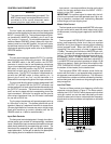
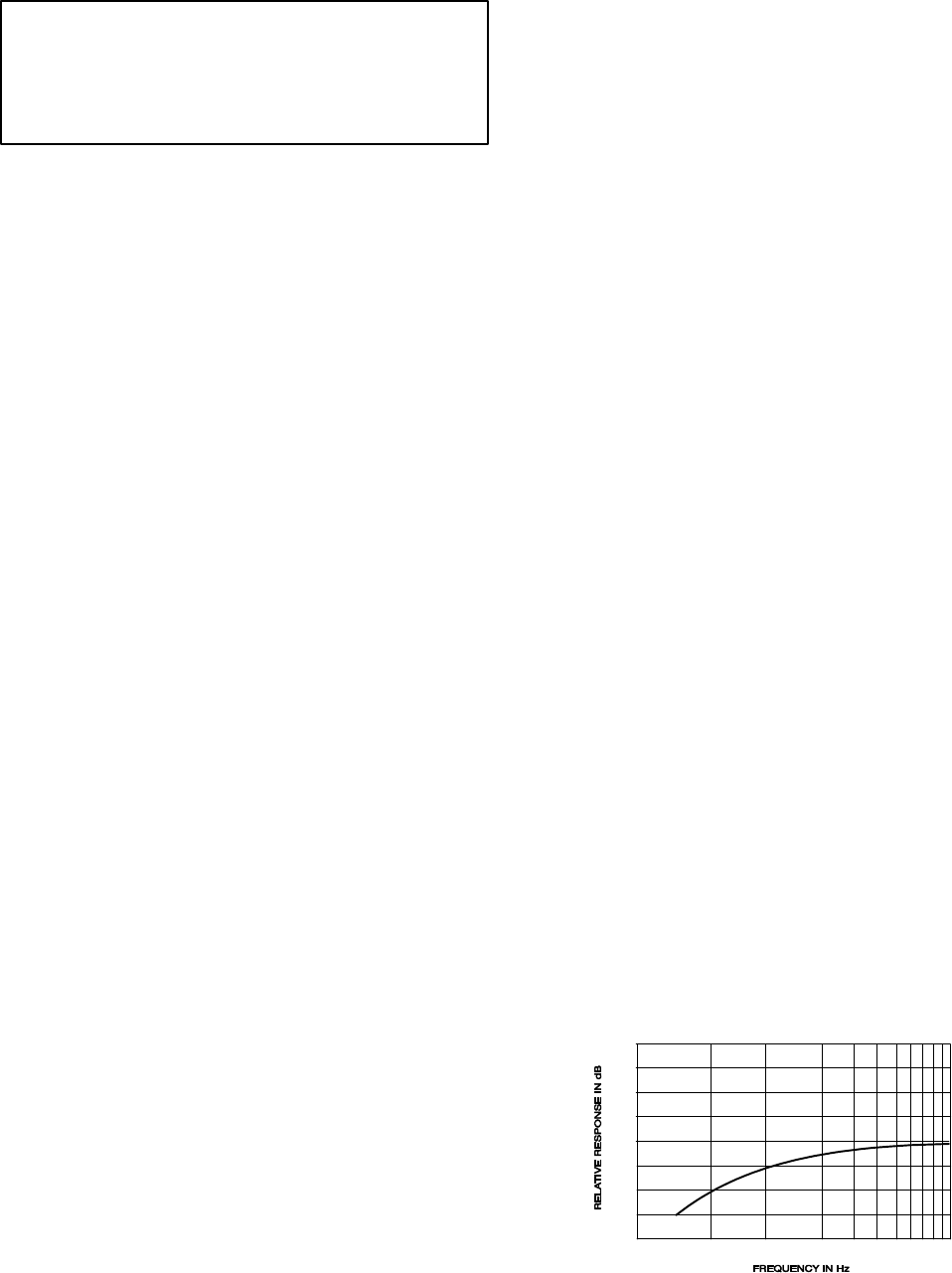
Low-Cut Filters
The low-cut filters provide a low-frequency rolloff to the
response curve as shown in Figure 2. The filters are acti-
vated by the LO-CUT IN/OUT switch above each individual
input gain control and can be used individually with each
control to reduce wind noise or undesirable low-frequency
signals such as from condenser microphones or turntable
rumble.
500
1,00050
100
200
20
0
–10
–20
LOW-CUT FILTER ACTION
FIGURE 2