


4
Mix Bus
Direct access to the mixing bus is provided through the
rear-panel MIX BUS phono pin jack. This provision is made
primarily to facilitate stacking or “multing” M267s to
achieve additional input capacity without losing any inputs.
With two M267s, for example, the two mixing buses are di-
rectly connected, providing two independent master gain
controls and two isolated line amplifiers with eight individu-
ally controlled inputs. Since the buses are directly paral-
leled, a 6 dB drop in gain will occur; and the master or input
controls must be increased to compensate. Noise specifi-
cations are not adversely affected by this interconnection.
Mix bus interconnection can also be made with other
Shure mixers, such as the M268, FP42. etc.
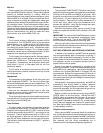
VU Meter
The VU meter is factory-calibrated for use with a 600 Ω
terminated line. The VU RANGE switch on the rear panel
selects either a +4 or +8 dBm output at 0 VU meter indica-
tion. (This switch changes the meter indication but does
not change the actual output level.) Microphone output
levels are 50 dB below line output. The +4 range is recom-
mended for normal use to provide approximately 14 dB of
headroom from operating level to clipping level.
The VU meter is illuminated by two No. 86 lamps operat-
ing well under their normal ratings for a life expectancy of
greater than 10,000 hours. The lamps are only lit during
ac operation. Consequently, the illumination serves as a
visual alarm if the ac is interrupted and the unit has
switched to battery.
The VU meter is connected on the primary side of the
output transformer to assure protection from any dc level
on a telephone line.
Headphones
The headphone outlet appears at the front-panel jack
panel designated PHONES. The two-circuit phone jack
will accommodate most stereo or mono headphones. The
output level is sufficient to provide high volume for use in
noisy environments.
Note that the headphone output level is also high
enough to use as an auxiliary unbalanced line feed to drive
a tape deck or a power amplifier.
The tip and ring connections of the headphone plugs are
in phase with pin 3 of all input and output connectors, and
with the tip of the MIX BUS jack.
Tone Oscillator
The highly stable, low-distortion tone oscillator provides
for line test and level checks. The oscillator is instantly ac-
tivated by the front-panel INPUT 1/OSC 1 switch; its level
can then be controlled by the INPUT 1 gain control on the
front panel. The tone oscillator frequency is 1,000 Hz, and
the signal appears on both the line and microphone out-
puts, as well as the headphone and mix bus connectors.
The oscillator should be switched off (INPUT 1 position)
when not in use.
Phantom Power
The rear-panel PHANTOM OFF/ON switch controls the
application of phantom power for condenser microphones,
such as the Shure SM81 and SM87A, to all inputs. With
the switch on and the rear-panel MIC/LINE switches in the
MIC positions, +30 Vdc is applied to pins 2 and 3 of each
input connection. Series current-limiting resistance is 3.3
kΩ for each input. When using other condenser micro-
phones with the M267, verify that the voltage and resis-
tance requirements are compatible.
Note that the phantom power cannot normally be ap-
plied to the inputs with the MIC/LINE switches in the LINE
position.
IMPORTANT: Do
not
turn the PHANTOM switch on when
using
unbalanced
low-impedance microphones; objec-
tionable hum will result. Turn off the PHANTOM switch
when condenser microphones are not being used.
Use only high-quality cable. Intermittent shorts between
broken shield wires and balanced conductors will cause of-
fensive noise transients in the system.
BATTERY OPERATION AND EXTERNAL POWERING
In addition to ac operation, the M267 can be operated
from an internal battery pack. Current drain is typically 17
mA at +8 dBm output level and typically 15 mA at + 4 dBm.
Battery power is recommended both for remote, on-loca-
tion operation, and as an emergency backup source in
case of failure of the ac power.
Access to the battery compartment is provided at the
bottom of the chassis. Three 9-volt alkaline batteries pow-
er the M267 at full rated output. Use alkaline batteries for
maximum life. Duracell MN1604A or Eveready 522 are
recommended. Battery life is approximately 20 hours at +4
dBm continuos use. Note that battery operation with phan-
tom power loads and high level headphone monitoring will
increase battery drain.
With batteries in the battery compartment, the M267 will
automatically and silently switch to battery operation
should the ac voltage fall below a suitable level. If the ac
power fails completely, the VU meter lamps will go out, pro-
viding a visual indication of line failure.
Battery condition can be determined by using the BATT
CHECK switch on the front panel. Activate the BATT
CHECK switch and observe the VU meter. A new set of
batteries will give about a +2 VU indication. Battery condi-
tion is good if the reading is above 0 VU; a lower reading
means that new batteries are required for proper opera-
tion. Note that the M267 power switch must be turned on
to check battery condition.
Telephone Interconnection
When using the M267 connected directly to a telephone
line, check to see whether the local telephone company re-
quires an interface coupler between the M267 and the tele-
phone line. If a coupler is required, make certain the cou-
pler selected and the wiring arrangement are in
compliance with the telephone company regulations.