


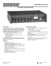

4
AC OPERATION
Use the supplied power adapter to connect the M367 to a power
outlet.
M367: 100-120 VAC, 50/60 Hz
M367E: 220-240 VAC, 50/60 Hz
The operating voltage can be switched internally (see Internal
Modifiable Functions).
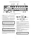
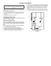
BATTERY OPERATION
Open the battery compartment by grasping the sides of the
compartment, squeezing to release the locks, and pulling the com-
partment outward. Insert two 9-volt batteries.
During battery operation, use the BATT CHECK button. Press
and hold to show battery level on the VU meter. Press once to illu-
minate the VU switch for 10 seconds, or set DIP switch 6 for con-
tinuous illumination (see DIP Switches).
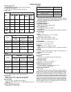
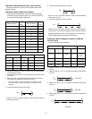
BATTERY LIFE
With two fresh 9-volt alkaline batteries, the M367 operates for
about eight hours. Some mixer features decrease battery life, as il-
lustrated in the following table.
*until Power LED begins to flash, allowing approximately 30 minutes
to replace batteries.
CONNECTING M367 OUTPUTS TO TELEPHONE LINES
Use the XLR outputs at line level to drive dc-biased, "dialed up"
telephone lines. A slight increase in distortion may occur. Use the
M367 limiter with the limiter threshold set to +4 dBm. Modify the
M367 output impedance to 600 W for proper fidelity (see Internal
Modifiable Functions). When connecting the M367 to a telephone
line, you must use an FCC-Registered interface adapter between
the mixer and telephone line.
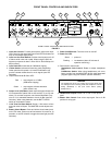
SETTING LEVELS
1. Set the MASTER gain knob to the full off position.
2. Activate the 1 khz tone oscillator by setting the 1 KHZ TONE
switch to ON. Adjust the MASTER gain until the VU meter
needle indicates "0". Adjust the input levels on the equipment
connected to the M367 outputs accordingly. Deactivate the
tone by setting the 1 KHZ TONE switch to OFF.
3. Adjust the Input gain controls based on the incoming signal
levels. The input PEAK LEDs should flicker red only on loud
input peaks.
4. Observe the output on the VU meter and adjust the MASTER
gain to obtain the desired levels. try to keep the average levels
around "0 VU". The PEAK LED adjacent to the VU meter
should illuminate only on loud output peaks.
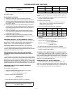
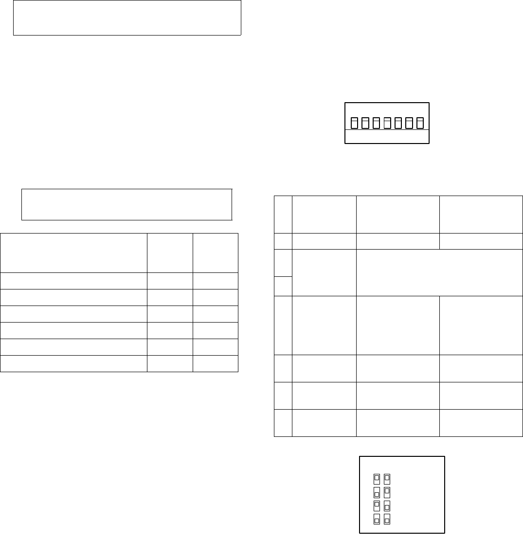
DIP SWITCHES
Access the DIP switches by removing the battery compartment
and top cover. Use the following table to set the switches
(Bold = factory setting.)
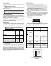
LIMITER THRESHOLD SETTINGS
FIGURE 4
NOTE
Momentary use of headphones or meter illumination will not
appreciably affect battery life.
Mixer Operation Battery
Current
(mA)
Battery
Life
(hours)*
No Signal 40 9
With +4 dBm continuous output 45 8
With six mics at 12 V phantom power 55 6.5
With six mics at 48 V phantom power 70 5
With output to headphones 50 7
With meter illumination continuously on 75 4.5
NOTE
Appliance inlet is the main disconnect device (to power off the
M367, you must unplug the power supply).
Switch
Function Up
Down
1 Meter 0 VU 0 VU = +4 dBm 0 VU = +8 dBm
2 Limiter
Threshold
See Figure 4
3
4 Program to
Monitor
Off On (adds attenu-
ated program signal
in headphones with
Pull/Monitor switch
on)
5 Monitor In
Gain
Normal High
6 VU Lamp (Batt
Check button)
Timed (Turns off
after 10 seconds)
Toggled (press on,
press off)
7 Phantom
Power
12 Vdc 48 Vdc
1
S701
234567
23
Limiter Threshold
= +16 dBm
= +8 dBm
= +4 dBm
= 0 dBm