


8
INTERNAL MODIFIABLE FUNCTIONS
Perform all modifications through solder points accessible on
the main PC board.
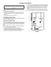
DISASSEMBLING THE M367
1. Remove the mixer top cover as previously described.
2. Carefully remove three multi-pin cable assembly connectors
from upper front PC board (nearest front panel). Remove the
three Phillips head screws securing the PC board. Remove up
per front PC board.
3. Carefully remove four multi-pin cable assembly connectors
from upper rear PC board (nearest rear panel). Remove the
three Phillips head screws securing the PC board. Remove
upper rear PC board.
4. Perform modification (refer to appropriate following proce-
dure). Note that all modifications can be performed without
removing the main PC board.
5. Reassemble M367 by performing above steps in reverse,
assembling the Phillips screws in the order indicated on the
upper front and upper rear PC boards.
CHANGING LINE LEVEL OUTPUT IMPEDANCE TO 600 W
Locate resistor R621 (near IC U602 pin 8) on the main PC board
and remove it. Locate empty pads X621 (near resistor R621).
Solder a 430 W, 1/2 W resistor through the holes at X621.
CHANGING UNSWITCHED LINE OUTPUT TO MIC LEVEL
Locate resistor R632 (near output transformer T601) and
remove. Locate empty pads X632 (near transformer T601). Solder
a jumper wire through the holes of X632.
CHANGING MIXER AUDIO LEVELS IN HEADPHONES
(Pull/Monitor Switch Activated, DIP Switch S701 Position
4 Closed)
Locate empty pads X649 (near Phones potentiometer R648).
Solder a 68 kW, 1/4 W resistor through the holes at X649 to hear
program audio 12 dB down from standard headphones level with
Pull/ Monitor switch on (pulled out). Solder a 24 kW, 1/4 W resistor
through the holes at X649 to hear program audio 6 dB from
standard headphones level with Pull/Monitor switch on (pulled out).
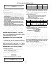
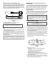
CHANGING LOW-CUT FILTER CORNER FREQUENCY
(3 DB DOWN POINT)
To decrease corner frequency:
1. Calculate new capacitor value for lower low-cut corner
frequency. Use the following formula:
C in mF= (85/frequency) - 0.33
Example: for 200 Hz corner frequency,
85/200 9 0.43
0.43 - 0.33 = 0.1
For 200 Hz corner frequency, use a 0.1 mF capacitor.
2. Locate the following empty pads:
Find all pads near ribbon cable assemblies W811, W812 and
W813.
3. Solder a new capacitor through the holes of the empty pads
for each channel to be modified.
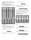
To increase corner frequency:
Note: Low-cut corner frequencies much higher than the factory
preset of 260 Hz may excessively attenuate desired low- to
mid-frequency program material.
1. Locate the following capacitors near empty pads:
2. Remove the indicated capacitor for each channel to be
modified.
3. Calculate new capacitor value for higher high-cut corner fre
quency. Use the following formula:
C in mF= (85/frequency)
Example: for 400 Hz corner frequency,
C = (85/400) = 0.21
For 400 Hz corner frequency, use a 0.22 mF capacitor.
4. Solder a new capacitor through the holes of the empty pads
for each channel to be modified.
SLOWING OUTPUT METER FROM "True VU" BALLISTICS
Locate empty pads X691 (at left of VU meter M1). Solder a 100
mF x 6.3 V electrolytic capacitor through the holes of X691. Ob-
serve capacitor polarity as marked on the PC board. The response
time is now 500 ms with no overshoot. To further slow the meter
response, use a larger capacitor value.
CHANGING MIC LEVEL OUTPUT IMPEDANCE
Locate resistor R631 (near output transformer T601) and
remove it. Locate empty pads X631 (near T601). Solder desired
value 1/4 W resistor through the holes of X631. For example, use
a 150 W, 1/4 W resistor for 150 W output impedance.
NOTE:
Capacitor must be non-polarized; ceramic or film type;
16V rating or higher.
NOTE
Only qualified service technicians should perform these
modifications.
Pad Channel Pad Channel
X421 1 X451 4
X431 2 X521 5
X441 3 X531 6
Capacitor
Pad
Channel
Capacitor Pad
Channel
C425
X421 1 C455 X451 4
C435
X431 2 C525 X521 5
C445
X441 3 C535 X531 6