


7
INTERNAL ADJUSTMENTS
These internal adjustments require only removal of the top
cover:
1. Remove battery compartment.
2. Remove four screws securing two plastic end caps and one
ground-bonding screw on the side opposite the battery com-
part ment.
3. Slowly slide cover up and off chassis.
VCA DISTORTION TRIMPOT (R607)
DO NOT ADJUST! This potentiometer is precisely calibrated on
each mixer for minimum distortion.
VU METER ADJUSTMENT (R684)
This trimpot adjusts the VU meter to indicate 0 VU at a preset
output level. The factory setting is +4 dBm. The user adjustment
range is -10 dBV to +4 dBm (-6 dBV to +8 dBm with DIP switch 1
down).
To set the VU meter to a value other than the factory setting
(0 VU = +4 dBm), proceed as follows:
1. Connect a 600 W load to an XLR output set for Line.
2. Connect an ac voltmeter with 1 MW or greater input
impedance (Fluke 77 or equivalent) in parallel with the load.
3. Set the 1 kHz tone oscillator switch to the ON position.
4. Adjust the 1 kHz tone oscillator level with the Master gain
con-
trol until the ac voltmeter reading is at the level desired
5. With the M367 top cover removed, adjust the VU Level Cali-
bration trim pot R684 with a screwdriver until the VU Meter
reads 0.
6. For 0 VU settings between +4 and +8 dBm, set internal DIP
switch S701 position 1 "down", and perform steps 1 through 5.
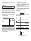
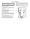
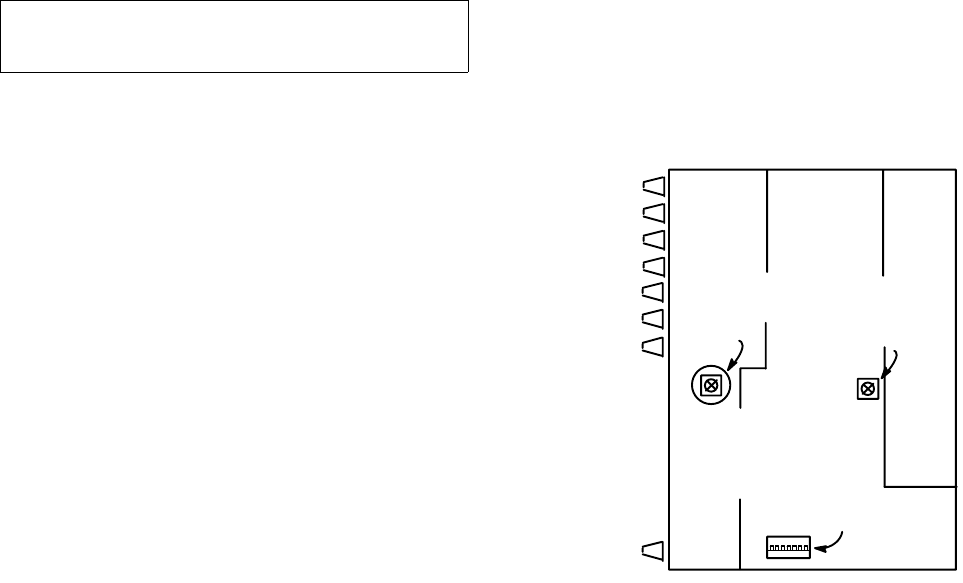
INTERNAL ADJUSTMENTS
FIGURE 5
NOTE
Only qualified service technicians should perform these
modifications.
VU METER
CALIBRATION
TRIMPOT
R684
VCA
DISTORTION
TRIMPOT
R607
DIP SWITCH
S701
(ACCESSED
THROUGH
HOLE IN
UPPER FRONT
PC BOARD)