


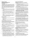

12
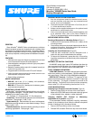
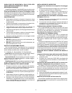
102.1 mm
(4 9/16 in.)
50.8 mm
(2 1/32 in.)
161.9 mm
(6 3/8 in.)
MX412D: 355.4 mm (14 in.)
MX418D: 501.7 mm (19
3
/
4
in.)
approximately 3 m
(10 ft)
FIGURE 5 • FIGURE 5 • ABBILDUNG 5
• FIGURA 5 • FIGURA 5
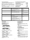
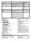
FIGURE 6
• FIGURE 6 • ABBILDUNG 6
FIGURA 6
• FIGURA 6
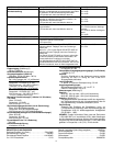
FIGURE 9
• FIGURE 9 • ABBILDUNG 9 • FIGURA 9 • FIGURA 9
RED (+)
ROUGE
ROT
ROJO
ROSSO
SHIELD
BLINDAGE
SCHILD
BLINDAJE
SCHEMATURA
BLACK-
NOIR
SCHWARZ-
NEGRO
NERO
ORANGE NARANJA ARANCIA
LED IN S ENTREE DEL S LED EIN
ENTRADA DE LED S INGRESSO LED
WHITE S BLANC S WEISS-
BLANCOS BLANCA
SWITCH OUT S COUPURE
AUSCHLATER AUS
SALIDAD DE INTERUPTER
USCITA INTERUTORE
GREEN S VERT S GRUN SVERONE
LOGIC GROUND S MASSE LOGIQUE S LOGISCHE ERDE
STIERRA DE CIRCUITOS LOGICOS S MASSA LOGICA
CABLE TYPE S TYPE DE CABLE S KABLTYP S TIPO DE CABLE
TIPO DE CAVO
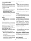
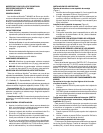
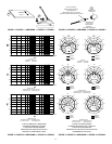
FIGURE 7 • FIGURE 7 • ABBILDUNG 7
FIGURA 7
• FIGURA 7
MIC
ELEMENT
220 pF
220 pF
FET
86E8958
W1
W2
W3
SHIELD BLINDAGE SCHILD BLINDAJE SCHERMATURA
RED ROUGE ROT ROJO ROSSO
BLACK NOIR SCHWARZ NEGRO NERO
FIGURE 8 • FIGURE 8 • ABBILDUNG 8
FIGURA 8
• FIGURA 8
MICROPHONE WIRING DIAGRAM
RED ROUGE ROT ROJO ROSSO
BLACK NOIR SCHWARZ NEGRO NERO
WHITE/SHIELD BLANC/BLINDAGE WEIß/SCHILD
BLANCO/BLINDAJE BIANCO/SCHERMATURA
BLACK NOIR SCHWARZ NEGRO SCHEMATURA
RED ROUGE ROT ROJO ROSSO
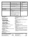
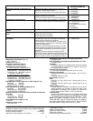
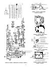
A.C. Voltage
D.C. Voltage
A.C. Voltage, Mic Off
D.C. Voltage, Mic Off
Printed Clrcuit Ground
Case Ground
(+) / (–) indicate A.C. polarity relative to input test signal.
NOTES:
3. 1. All resistors1/10 Watt, 1%, 0805 unless. . . . .
otherwise specified.
4. 2. Electrolytic capacitors shown in µF, ±10%,. . . . .
50V or more, unless otherwise specified.
5. 3. The elements U1E and U2C designate Pow-. . . . .
er (+Vcc) and Ground Terminals only the corresponding
ICs.
6. 4. The following symbols denote:. . . . .
7. 5. All voltages measured with a meter or oscilli-. . . . .
scope having 10 megaohm or greater input impedance with
preamp input driven by a 0.1 Vrms, 1kHz signal through the
test circuit shown below. A Shure M367 mixer or equivalent,
with 48 V phantom power switched on, supplies the required
power and load to the preamp. Values shown may vary +/–
20%.
8. 6. Standard symbols indicate voltages for mic on.. . . .
Symbols with dark edges indicate voltages for mic off (see note
4). Note: Mic is truned off by holding the membrane switch
closed, shorting J4.
0.1 Vrms
1 kHz
TEST CIRCUIT
W2
W3
W1
30.1 K
1.82 K
10 µF, 10V
+Vcc
+Vcc
+Vcc
+Vcc
+Vcc+Vcc
+Vcc
+Vcc
+Vcc
+Vcc
+Vcc
+Vcc
+Vcc
+Vcc
NOT INSTALLED
Logic Ground