


12
SUGGESTED LOGIC APPLICATIONS
This section contains suggestions on the uses of the
SCM410’s logic capabilities. Note that uses of these functions
are not limited to the listed applications. The user is limited only
by imagination and creativity. For additional suggestions and
solutions to installation problems, contact the Shure Applica-
tions Department.
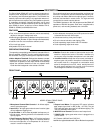
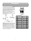
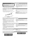
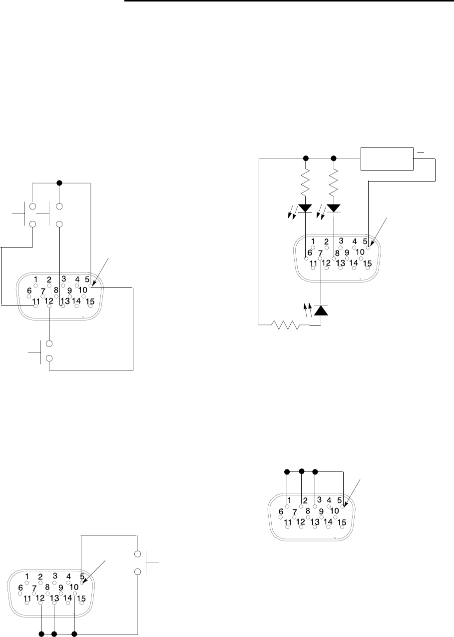
Cough Button
The talker can turn off his or her microphone during coughing
or private conversations by installing an SPST pushbutton
switch between the MUTE IN and Logic Ground pins for each
channel to be modified (see Figure 20). When a channel is
muted, no audio is passed. (See
Dead Zone on MUTE IN De-
feat
paragraph
in the
Internal Modifications
section for more in-
formation on MUTE IN logic.)
M1
M3
M2
LOGIC
GROUND
COUGH BUTTONS
FIGURE 20
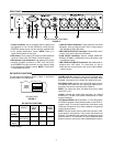
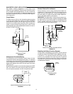
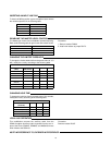
Chairperson-Controlled Muting
The chairperson can, by activating a switch, silence all other
microphones and be heard without interruption. For operation
in this mode, connect all the MUTE IN pins together
except that
of the chairperson’s channel
, and wire an SPST pushbutton or
toggle switch between those MUTE IN and Logic Ground pins
(see Figure 21).
An alternative to a switch is to connect the chairperson’s GATE
OUT to the MUTE IN of other channels. When the chairper-
son’s microphone activates, all other microphones mute.
M2 M3
M4
LOGIC
GROUND
CHAIRPERSON-CONTROLLED MUTING
FIGURE 21
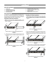
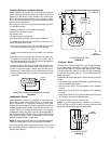
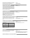
Remote Channel-On Indicators
Remote indicators can be used to indicate when a talker’s mi-
crophone is on. Connect the LEDs and a 5-volt supply to the
GATE OUT pins (See Figure 22). To avoid switching clicks in
the audio output,
do not
ground the power supply negative ter-
minal in the audio system or rack ground.
IMPORTANT: If a single cable is used for the microphone au-
dio signal
and
the LED dc power, separate shielded pairs must
be used. Failure to carry the dc power on a shielded pair may
result in audible clicking due to capacitive coupling between
the dc power lines and microphone lines.
5 V POWER
SUPPLY
+
G1 G3
470 Ω,
1/4 W
470 Ω,
1/4 W
470 Ω,
1/4 W
G2
LOGIC
GROUND
REMOTE CHANNEL-ON INDICATORS
FIGURE 22
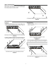
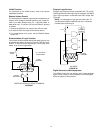
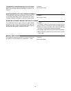
Disabling the Gating Function (Bypass)
To keep certain microphones on at all times, wire the desired
microphone channel’s OVERRIDE IN pins together to the Log-
ic Ground pin. The selected channels now function as they
would in a non-automatic mixer (see Figure 23). To perform
this modification internally on the mixer, refer to the
Shorting
Override In to Logic Ground Internally
paragraph in the
Inter-
nal Modifications
section.
O2O1 O3
LOGIC
GROUND
GATING BYPASS
FIGURE 23