


7
SCM410 CONNECTIONS
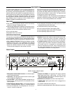
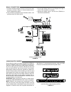
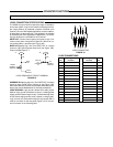
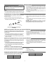
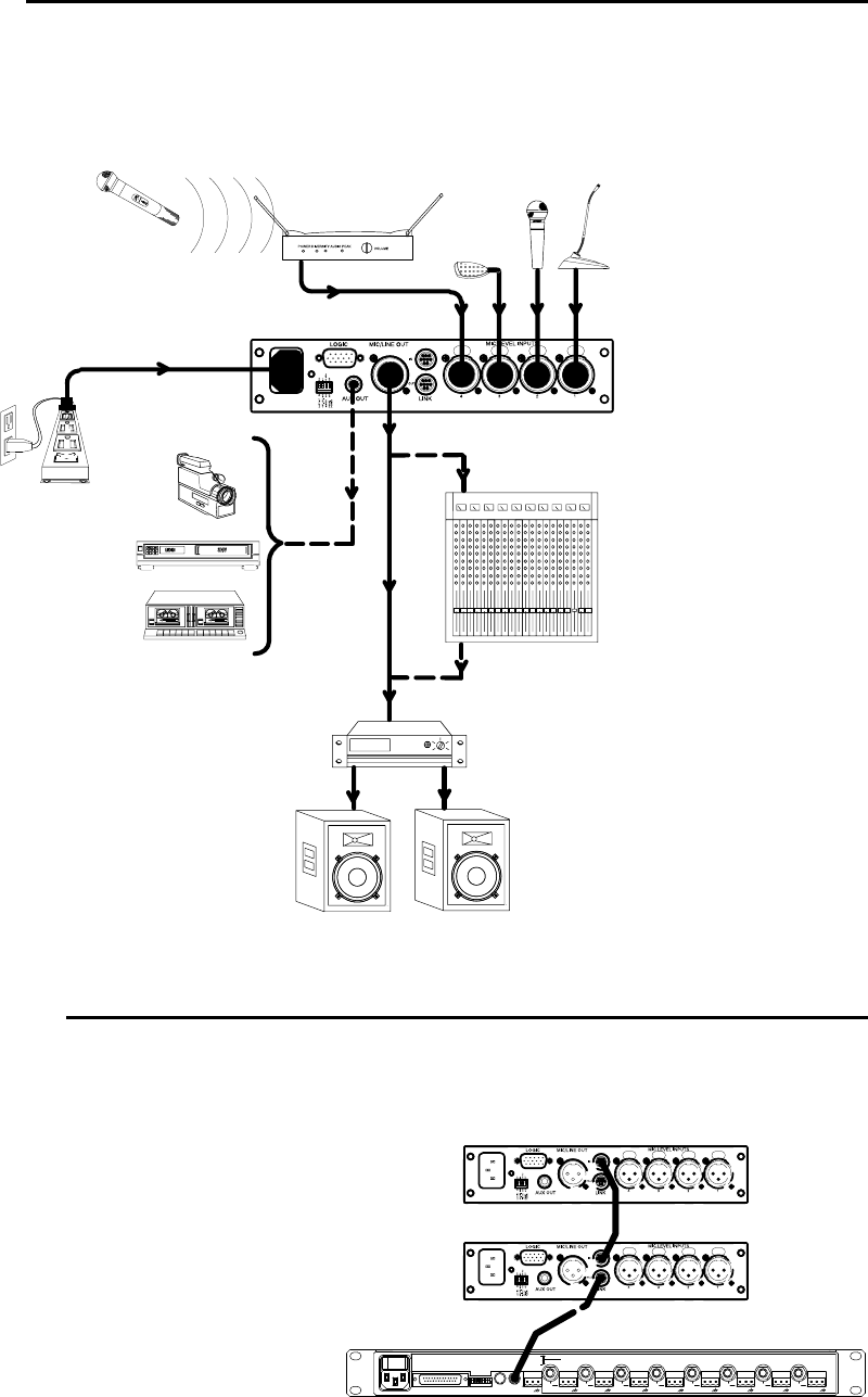
1.Connect microphone signal sources to the Channel Input
connectors, as shown in Figure 14. Use conventional 2-con-
ductor shielded audio cables.
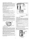
2.If any condenser microphones are connected, set the +12V
phantom power DIP switch to ON.
3.Connect the SCM410 Mic/Line Level Output to the input of
mixers, EQs, amplifiers or recorders.
4.Connect the power cord to 100–120 Vac (SCM410) or
220–240 Vac (SCM410E).
SHURE
OR
SCM410 CONNECTIONS
FIGURE 14
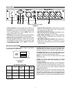
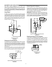
LINKING MULTIPLE MIXERS
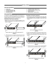
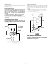
If more than four inputs are needed, multiple Shure SCM410,
FP410, or SCM810 mixers can be linked by connecting the
LINK OUT of the first mixer to the LINK IN of the next mixer,
and so on. See Figure 15. Leave the LINK IN jack of the
first
mixer and the LINK OUT jack of the
last
mixer unconnected.
When properly linked, the mixers will operate as a system. Au-
tomatic mixing functions will be shared by all units. All input
signals appear at all linked mixer outputs. Each mixer’s Master
level control only controls its own output. However, actual off-
attenuation will increase as more mixers are linked. This re-
duces excessive noise and reverberation contributed by the
increased number of microphones.
IMPORTANT: When using logic terminals on linked mixers,
connect the LOGIC GROUND terminals of each unit together.
NOTE: SCM410 link connections are unbalanced. To mini-
mize hum and noise, avoid using longer link cables. Use high
quality, shielded cable, and keep them away from sources of
magnetic or electrical noise, such as power transformers or
light dimmers. To minimize ground currents, make sure linked
mixers are connected to the same AC power mains.
Ć
Ć
Ć Ć Ć Ć Ć
Ć
LINKED SCM410 AND SCM810 MIXERS
FIGURE 15