


3
DESCRIPTION
The Shure Model SCM800 is a full-featured, eight-channel mi-
crophone mixer for sound reinforcement, general audio re-
cording, and audio-visual systems. Any low-impedance, bal-
anced dynamic or condenser microphone, including a wire-
less microphone system, can be used with the SCM800 mixer.
Each SCM800 accepts up to eight microphone- or line–level
inputs and one aux-level input (two input jacks feed the same
channel). Up to four SCM800 mixers can be linked to provide
up to 32 input channels. Each input channel has a two-band
equalizer, switchable microphone- or line-level operation,
switchable 48 V phantom power, and a
1
/
4
-inch send/receive
insert jack.
The SCM800 operates on 120 Vac power; the SCM800E oper-
ates 230 Vac power. Both models are supplied with rack-
mounting hardware, link cable and removable block terminal
connectors. An accessory rack panel adapter (Model
RKC800, available separately) converts the removable block
input and output connectors to XLR connectors, and the Aux
connectors to phono jacks.
FEATURES
S Compatible with Shure SCM810 and FP410 automatic mi-
crophone mixers
S Adjustable EQ per channel: low-frequency rolloff and high-
frequency shelving
S 48 V phantom power selectable for each input
S Active balanced microphone- and line-level inputs and line-
level output
S Highly RF-resistant chassis and circuitry
S LED indication of channel clipping
S Linking capability for systems up to 32 microphones
S Two Aux-level input jacks that feed one channel
S Insert jack on each channel
S Manual mixing of input channels
S Internal Modification permits 230 V operation (SCM800) or
120 V operation (SCM800E)
S Front-panel headphones output with level control
S Peak-responding output limiter with selectable thresholds
and LED indicator
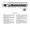
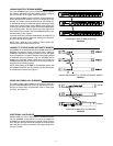
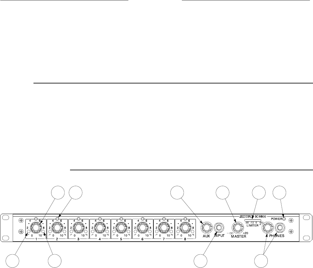
SCM800 FRONT PANEL
1 2 5 7 8 10
4
3 6 9
MODEL SCM800/E FRONT PANEL
FIGURE 1
1. Microphone Channel Gain Controls 1 - 8: Allows ad-
justment of microphone gain.
2. Input LED 1 - 8: Lights red at 6 dB below clipping level.
3. Low-Cut Filter 1 - 8: Recessed screwdriver adjustment
provides adjustable low-frequency rolloff (high pass) to
reduce undesirable low-frequency signals.
4. High-Frequency Shelving Filter 1 - 8: Recessed screw-
driver adjustment provides level boost or cut in mid/high-
frequency region for compensation of off-axis lavalier mi-
crophones, or for cutting the high-frequency sibilance of
vocal microphones.
5. AUX Level Control: Sets the input level for aux-level
equipment connected to the adjacent
1
/
4
-inch phone jack
INPUT or rear-panel
1
/
4
-inch AUX input.
6. AUX INPUT
1
/
4
-inch Phone Jack: Mixes external auxil-
iary- or line-level sources, i.e., tape recorders, into output.
Signal appears at output of all linked mixers.
7. MASTER Level Control: Determines the overall mix level.
8. Output Level Meter: Nine-segment LED meter indicates
peak output signal level. Last LED indicates limiter action.
9. PHONES Control and
1
/
4
-inch Phone Jack: Permits
monitoring of mixer output through headphones.
PHONES control determines headphones output level.
10. POWER LED: Lights green when unit is powered.