


44
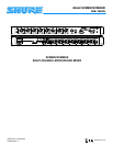
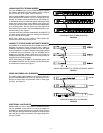
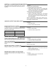
SCM800 REAR PANEL
INSERT
+
AUX IN
INSERT
IN
LINK
MIC/PHM/LINE
LINK
123456
SWITCH
(SWITCH)
AUX/INS/INS
LINE
OUTPUT
OUT
Ć
+
78
120VAC 50/60 Hz 200mA
18
13
Ć
+
Ć
+
Ć Ć
+
Ć
+
Ć
+
+
MIC/PHM/LINE
SWITCH
INSERT
MIC/PHM/LINE
SWITCH
INSERT
MIC/PHM/LINE
SWITCH
INSERT
MIC/PHM/LINE
SWITCH
INSERT
MIC/PHM/LINE
SWITCH
MIC/PHM/LINE
SWITCH
INSERT
MIC/PHM/LINE
SWITCH
Ć
11 12 17
16
14 15
PHANTOM
(PHM)
MICĆ
LEVEL
(MIC)
LINEĆ
LEVEL
(LINE)
Ć
+
(SWITCH BEHIND
CONNECTOR)
INSERT
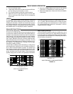
MODEL SCM800/E REAR PANEL
FIGURE 2
11. SCM800: 120 VAC Power Connector and Rocker
Switch: Switch turns unit on when power cord is plugged
into 120 Vac. Can be internally changed to 230 V opera-
tion (see Voltage Selection).
SCM800E: 230 VAC Power Connector and Rocker
Switch: Switch turns unit on when power cord is plugged
into 230 Vac. Can be internally changed to 120 V opera-
tion (see Voltage Selection).
12. DIP Switch: The 7-position DIP switch provides control
of the output limiter threshold (see DIP Switches).
13. LINK IN/OUT Jacks: Permit multiple SCM800 mixers to
be stacked for additional inputs.
14. LINE OUTPUT Removable Block Connector: Active
balanced line-level signal for connection to amplifiers, re-
corders or other mixers. If necessary, output level can be
changed to microphone level. Refer to the Internal Modifi-
cations section of this manual.
15. SEND/RECEIVE
1
/
4
-inch Insert Jacks: Post-fader,
post-EQ insert point to add external compressor/limiter,
graphic or parametric EQ, or other signal processors. Tip
is send, ring is return. Can be modified for use as a Direct
Out (see Internal Modifications).
16. AUX/INS/INS 3-Position Slide Switch: Selects either
aux input function or insert function for channel 8 (only) In-
sert jack. Left switch position is AUX IN; center and right
positions are INSERT. This switch is located behind Line
Output connector.
17. INPUT 1-8 Removable Block Connectors: Active bal-
anced microphone- or line-level inputs.
18. Input 1 - 8 MIC/PHM/LINE 3-Position Slide Switch: Se-
lects operation at either microphone-level (left), micro-
phone-level with 48 V phantom power (center), or line-lev-
el (right) signals. This switch is located behind the remov-
able block connector.