


9
INTERNAL MODIFICATIONS
WARNING: All modifications must be performed by quali-
fied service technicians. Voltages in this equipment are haz-
ardous to life. No user-serviceable parts inside. Refer all
servicing to qualified service personnel. The safety certifica-
tions of the SCM800 do not apply when the operating volt-
age is changed from the factory setting.
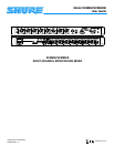
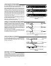
ABOUT PRINTED CIRCUIT BOARD MODIFICATIONS
S A jumper is represented by “X” on the printed circuit
board legend, a resistor is represented by an “R.”
S The first number in the reference designator indicates
the channel number; i.e., R1027 refers to a Channel 1
resistor, and X7216 refers to a Channel 7 jumper, etc.
S Components in the Master section are preceded by
the number “9” (X901, etc.).
S The circuit board contains holes where resistors are
to be added.
S A single drop of solder can serve as a jumper between
adjacent jumper pads.
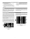
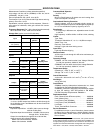
S All Channel modifications in this section use
Channel 1 as an example.
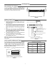
REMOVING THE TOP COVER
To gain access to the main printed circuit board, remove the
eight Phillips head screws securing the top cover to the chas-
sis and remove it. Most internal modifications can be made
from the top of the main board.
MODIFYING THE SCM800 FOR 220–240 VAC, 50/60 HZ OPERATION
The SCM800 can be internally modified to operate on 230 Vac,
50/60 Hz power.
NOTE: The supplied cord uses Harmonized IEC Cordage with
the following color coding: Brown = Line, Blue = Neutral,
Green/Yellow = Ground. For systems requiring other mains
connectors, obtain a power cord with an IEC 320 type mating
connector for connection to the SCM800, and an appropriate
plug on the other end for connection to the mains.
Procedure:
1. Disconnect the SCM800 from the AC power source.
2. Remove the top cover.
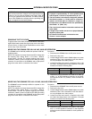
3. Locate Voltage Selector switch SW903 adjacent to power
transformer T901. Use a screwdriver to turn the center ro-
tor on the SW903 to the 230V position.
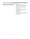
4. Locate Fuse F901 and remove it. Replace it with a 100
mA, 250 V, time delay fuse for 230V operation. Fuse part
numbers are listed in following table:
Fuse Type Shure Part No. Littelfuse Part No.
100 mA, 250 V 80C258 218.100
200 mA, 250 V 80BC8196 239.200
5. Replace the power cord with a cord rated for for 230V op-
eration, i.e., an IEC appliance connector on the equip-
ment end and a CEE 7/7 (“Schuko”) mains connector on
the other.
MODIFYING THE SCM800E FOR 100–120 VAC, 50/60 HZ OPERATION
The SCM800E can be internally modified to operate on 120
Vac, 50/60 Hz power.
NOTE: The supplied cord uses Harmonized IEC Cordage with
the following color coding: Brown = Line, Blue = Neutral,
Green/Yellow = Ground. For systems requiring other mains
connectors, obtain a power cord with an IEC 320 type mating
connector for connection to the SCM800E, and an appropriate
plug on the other end for connection to the mains.
Procedure:
1. Disconnect the SCM800E from the AC power source.
2. Remove the top cover.
3. Locate Voltage Selector switch SW903 adjacent to power
transformer T901. Use a screwdriver to turn the center ro-
tor on the SW903 to the 120V position.
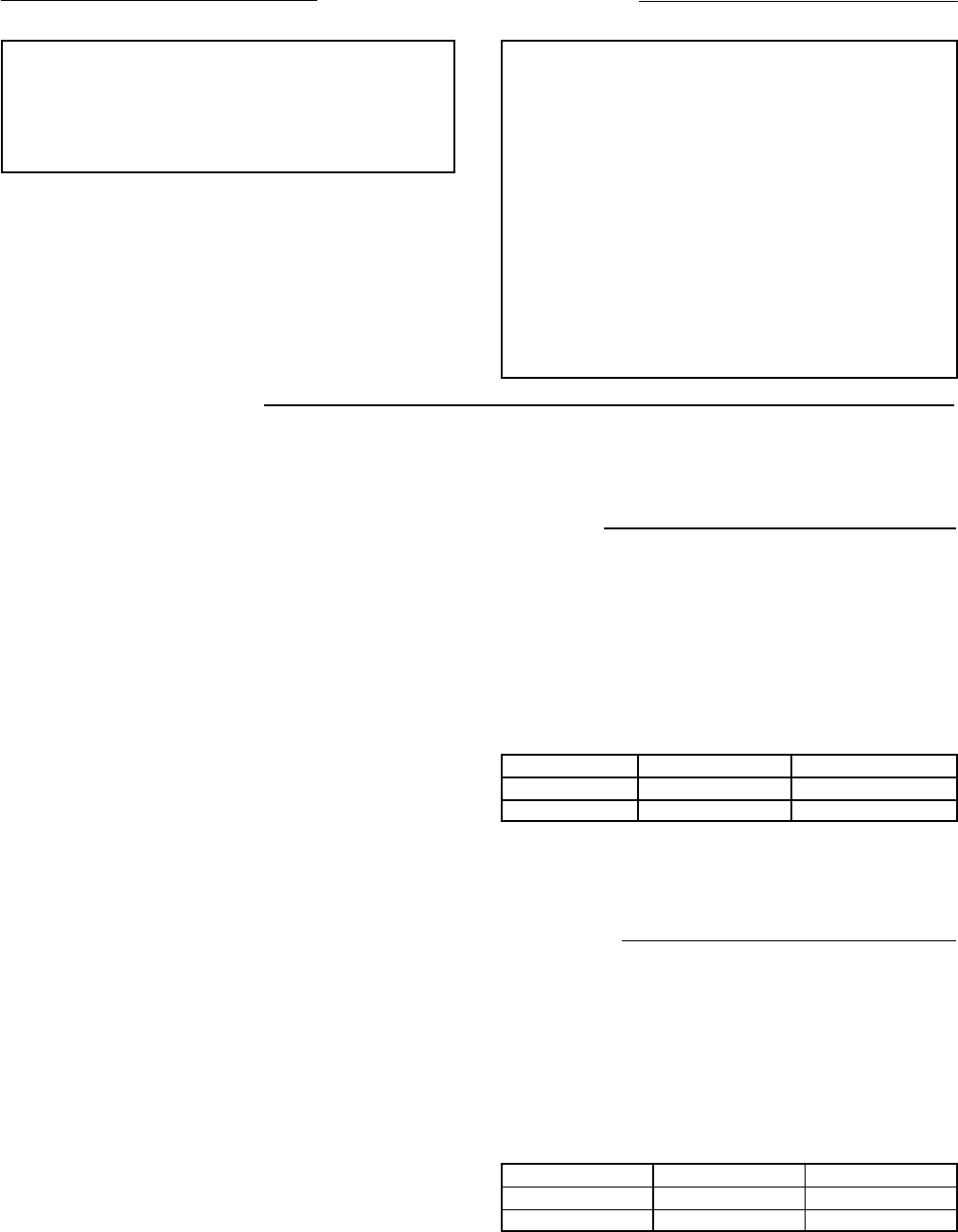
4. Locate Fuse F901 and remove it. Replace it with a 200
mA, 250 V time delay fuse for 120 V operation. Fuse part
numbers are listed in the following table:
Fuse Type Shure Part No. Littelfuse Part No.
200 mA, 250 V 80BC8196 239.200
100 mA, 250 V 80C258 218.100
5. Replace the power cord with a cord rated for 120V opera-
tion, i.e., an IEC appliance connector on the equipment
end and a mains connector suitable for 120V operation on
the other.