


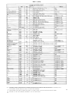


SERVICE INSTRUCTIONS (Cont’d)
PROCEDURE:
First, the meter (7) must be mechanically set to zero.
Turn the Power switch (11) OFF and wait one minute. The
meter pointer should rest over the mark at the left-hand
end of the scale, left of the -20 VU and 0 dB Compression
line. Using a small blade screwdriver, rotate the black
plastic screw below the meter face to set the pointer, if
necessary. The electrical calibrations may now be per-
formed as outlined below.
Unless otherwise specified, set all Lo-cut Filter switches
(2) to IN, the Meter switch (8) to DB COMP., the Power (11),
Gated Memory (21), and Comp. (22) switches to ON, the
Input (14) and Output (17) switches to LINE, and the VU
Range switch (4) to +4. Set Output (3) and Input (1) con-
trols to 0, except for Input 1 (1A), adjusted as above. Set
Response Rate control (6) to 3. Measure all voltages with
respect to chassis ground.
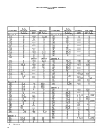
GATED MEMORY CALIBRATION:
The Gated Memory calibration should be checked and
adjusted before proceeding to the compression system
calibration.
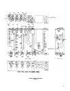
Connect meter probe to P.C. Board 3, terminal A,
leaving existing gray wire connected, to measure E3A.
Adjust input such that E3A is -43.5 dBV (6.6 mV).
Red portion of Gated Memory indicator (5) should be
exposed.
Adjust input such that E3A is -41.5 dBV (8.4 mV).
Red portion of Gated Memory indicator (5) should be
covered by white vane.
If steps 2 and 3 are not correct, adjust input such that
E3A is -42.5 dBV (7.5 mV) and rotate R318 fully
counterclockwise. Gated Memory indicator (5) will be
white. Slowly rotate R318 clockwise just until red
portion of Gated Memory indicator is exposed. Re-
check steps 2 and 3.
COMPRESSION SYSTEM CALIBRATION:
Because of the interdependence of trimmer settings, the
following procedure must be followed in the order listed.
The Gated Memory must first be properly calibrated as
outlined above.
The voltage at terminal L, P.C. Board 4, referred to as
E4L, must also be measured. This terminal is a test point
with no wire connected to it, and access may most easily
be obtained by setting the chassis on its right or left end
and inserting the meter probe from the chassis bottom
through the rectangular hole near transformers T4 and T5.
The temporary wiring change in step 2 may also most
easily be done from the bottom of the unit.
Average Level Adjustment (R212).
Set input such that E3A is -30 dBV (31.6 mV). Voltage
E4L must be -40 ± 0.2 dBV (10± 0.2 mV). If neces-
sary, adjust R212 for the proper E4L reading, but allow
15 seconds of settling time after moving R212 setting
to read E4L. If this setting is changed, all subsequent
calibration steps must be checked.
Peak Level Adjustment (R211).
Move blue wire from terminal C of P.C. Board 2 to
terminal D. Set input such that E3A is -20 dBV (100
mV). Voltage E4L must be -27.5 ± 0.3 dbV (44 ± 3
mV). If necessary, adjust R211 for proper E4L reading.
Return blue wire from terminal D of P.C. Board 2 to
terminal C.
DB Compression Meter Calibration Check.
A. Set input such that E3A is -40 dBV (10 mV).
B.
C.
Meter pointer should lie over 0 on the DB Com-
pression scale.
Set input such that E3A is -20 dBV (100 mV).
Meter pointer should lie in region occupied by
20 on the DB Compression scale. If either of these
checks is not correct, proceed to step 4.
Set input such that E3A is 0 dBV (1.0 V). Meter
pointer should lie in region occupied by 40 on the
DB Compression scale. If checks A and B are
correct, but if this check is not, proceed to step 5.
4. DB Compression Meter Calibration, 0 and 20 Points
(R213, R214).
The settings of R213 and R214 interact to calibrate the
meter to read 0 when E3A is -40 dBV (10 mV) and to
read 20 when E3A is -20 dBV (100 mV).
A. Rotate R215 fully clockwise.
B. Set input such that E3A is -40 dBV (10 mV). Ro-
tate R213 for a meter reading of 0.
C. Set input such that E3A is -20 dBV (100 mV). If
meter reading is less than 20, rotate R214 slightly
clockwise. If meter reading is more than 20, rotate
R214 slightly counterclockwise. The effect upon
the meter reading at this point is unimportant.
D. Set input such that E3A is -40 dBV (10 mV) and
again rotate R213 for a meter reading of 0.
E. Again set input such that E3A is -20 dBV (100 mV)
and observe meter for a reading of 20.
F. Repeat steps B through E until meter reads 0 when
E3A is -40 dBV (10 mV) and 20 when E3A is -20
dBV (100 mV).
G. Proceed to step 5.
5. DB Compression Meter Calibration, 40 Point (R215).
Set input such that E3A is 0 dBV (1.0 V). Rotate R215
until meter reads 40 on the DB Compression scale.
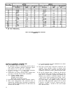
VU METER CALIBRATION:
Proper VU meter calibration is determined by a VU
CAL trimmer potentiometer (R529) on P.C. Board 5. The
check outlined in step 1 may be performed if P.C. Board 5
has not been replaced, but the procedure of step 2 must
be followed if it has been changed.
First, connect a 600-ohm ± 5%, ½ watt resistor (two
1200-ohm, 5%, ¼ watt resistors in parallel may be used)
between terminals 3 and 2 of the Line Output connector
(20).
1. Calibration check.
A.
B.
C.
Set input so that meter reads approximately 20 on
the DB Compression scale, with the Meter switch
(8) set to DB COMP.
Set the Meter switch (8) to VU and rotate the Out-
put control (3) until the meter reads 0 on the VU
scale.
The voltage measured across the 600 ohm resistor
should be 1.8 ± 0.3 dBV (1.23 ± 0.04 V). This is
4.0 ± 0.3 dBm.
2. Calibration procedure.
If meter Ml has been replaced, first check calibration
in step 1. If check fails, follow procedure below.
A. Set input such that meter reads approximately 20
on the DB Compression scale, with the Meter
switch (8) set to DB COMP.
B. Set the Output control (3) such that the voltage
measured across the 600-ohm resistor connected
to the Output terminals (20) is 1.8 dBV (1.23 V or
4.0 dBm).
27