


SPECIFICATIONS (Cont’d)
(11)
Battery Operation:
27 volts nominal, 21.5 volts minimum. Current con-
sumption at 27 volts, 10 ma. at no signal; 12 ma. at
20 dB compression and +8 dBm output.
Battery Life:
Power Switch: Controls ac, external dc and internal
battery power applied to the unit, but will not prevent
power from being drawn from the internal batteries by
a load connected to 30 Volts DC jacks (26) when
switched to OFF.
REAR PANEL
Mix Bus Jack: Phono pin jack allows adding inputs by
interconnecting to a similar jack on another SE30
or M67 Mixer.
Estimated 80 hours at 4 hours use per day.
Battery Complement:
9 volt, 6 Eveready type 222 or 216 or equivalent.
(13)
One heavy-duty 1.5 volt “D” size cell, Eveready type
D99 or equivalent to power Aux. Light approximately
8 hours continuously.
(14)
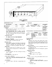
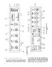
CONTROL AND CONNECTOR
DESCRIPTIONS (See Figure 2)
(15)
(1)
(2)
(3)
(4)
(5)
(6)
(7)
(8)
(9)
Input Controls: Control gain of individual input stages
to adjust relative levels between inputs and to adjust
amount of compression. Input 1 (1A) also controls
Tone Oscillator level when used.
Lo-cut Filter Switches: Low frequency response is re-
duced by 6 dB per octave below approximately 150 Hz
with switch set to IN. Input 1 switch (2A) also activates
tone oscillator.
Output Control: Controls output level when unit is
used in compression or acts as a master gain control
when compression is disabled. May be used for over-
all fading. Does not affect amount of compression.
VU Range Switch: Selects meter sensitivity so 0 VU
indicates results from either +4 dBm or +8 dBm line
output level.
Gated Memory Indicator: Will be red when Gated
Memory is “holding” prior amount of compression
during a low input signal. Will be white whenever in-
put signal is above compression threshold, or if either
Gated Memory or compression is disabled. Illumi-
nated by ac operated lamps or independent battery
operated auxiliary light.
Response Rate Control: Adjusts time constant of
compression system to compensate for different types
of program material. Generally, a faster setting (lower
numbers) results in a more constant output level but
a more audible compression effect. Setting this con-
trol is a subjective matter, but the following guide-
lines may be used:
Meter: Indicates either VU output level (upper VU
scale) or compression due to input signal above thres-
hold by the amount indicated (lower DB Compression
scale). VU meter isolated from dc on line output. Il-
luminated by ac operated lamps or independent bat-
tery operated auxiliary light.
Meter Switch: Selects function of meter for VU out-
put level or DB Compression.
Battery Check Switch: Spring-return switch overrides
Meter switch, allows checking battery condition with-
out affecting operation of unit. A reading of 0 VU indi-
cates end-of-life.
(10) Aux. Light Switch: Spring-return switch allows illu-
Line Output Terminals: Thumbscrews for direct wire
connections to balanced line, wired in parallel with
three-pin Output connector (16) in LINE position of
switch only. Phase is indicated by pin number ref-
erences, and a ground thumbscrew is provided.
Gated Memory Switch: Will disable Gated Memory
function without affecting other operation.
Compression Switch: Will disable compression and
Gated Memory functions of the SE30, converting it to
a high-quality linear mixer and remote amplifier.
Stereo Parallel Jack: Phono pin jack allows two units
to be synchronized to compress equally the channel
sum (L + R) signal. See Service section.
Battery Compartment: Requires six readily available
O-volt batteries (Eveready type 222 or 216 or equiva-
mination of meter and Gated Memory indicator from
lent) wired in series-parallel for 27 volts dc and one
internal battery.
heavy-duty D cell (Eveready type D99 or equivalent)
*Designed to mate with Cannon XL series, Switchcraft A3 (Q. G.) series. or equivalent connector.
5
(16)
(17)
(18)
(19)
(20)
(21)
(22)
(23)
(24)
Input Connectors: Female professional three-pin au-
dio connectors* accept balanced low-impedance mi-
crophone or high-level line inputs. Wired with pins
2 and 3 “hot” and pin 1 ground.
Mic/Line Input Switches: Select either microphone
or line level input sensitivity for each input.
Aux. Line Input Jack: Three-conductor (tip, ring,
sleeve) phone jack provides a second balanced line
input for Input 1. May be used in conjunction with, or
instead of, three-pin input connector when input
switch (14A) is set to LINE. Inserting a two-conductor
phone plug will automatically unbalance the input
without otherwise affecting operation. Tip and ring
are “hot,” sleeve is ground, and tip is in phase with
pin 2 of input and output.
Output Connector: Male professional three-pin audio
connector* provides balanced output at either line
level or microphone level (50 dB below line level).
Wired with pins 2 and 3 “hot” and pin 1 ground, in
phase with input connectors.
Mic/Line Output Switch: Selects either microphone
or line level output at output connector.
Aux. Output: Two-conductor (tip-sleeve) phone jack
provides isolated unbalanced aux. level (20 dB below
line level) output, for use with tape and cassette re-
corders and power amplifiers with high level, high
impedance inputs. Tip of jack is in phase with tip of
Aux. Line Input jack (15).
Headphone Jack: Three-conductor (tip, ring, sleeve)
phone jack wired to provide two different output levels
for 600 to 2,000 ohm headphones. If a two-conductor
(tip, sleeve) phone jack is inserted partially (to the first
detent), output will be approximately .18 volts into
1,000 ohms at +4 dBm output. If the plug is inserted
fully, the voltage will be approximately .38 volts. If
stereo headphones are used, signal will appear in both
phones. The tip and ring are in phase with pin 3 of
the input and output.