


MODIFICATIONS
Noise Improvement for Single Inputs:
The overall signal-to-noise ratio of the SE30 may be im-
proved for single-input applications by disabling the two
unused input channels. This automatically reduces the
noise level of the mixing circuitry without changing the
gain or other characteristics of the remaining input. It is
recommended that Input 1 be used and Inputs 2 and 3 dis-
abled to retain the Tone Oscillator and Aux. Line Input
features associated with Input 1. To disable Inputs 2 and 3,
follow the procedure below.
1. Remove AC line cord and turn off all power. Remove
the top cover.
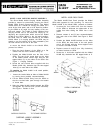
2.
Locate resistors R12 and R13 (33K ohms), between In-
put 2 and 3 controls and their associated Lo-cut Filter
switches. Disconnect resistors R12 and R13 from
switches S2 and S3. Bend removed lead of resistor
away from all terminals, wires, and chassis.
3. Replace top cover. During operation, set Input 2 and
Input 3 controls to zero.
Response Rate Knob Removal:
To prevent inadvertent misadjustment of the Response
Rate Control for applications in which a fixed setting may
be established, the knob may be removed.
1. Experimentally determine the proper Response Rate
Control setting for the intended application and rotate
the knob to this position.
2. Remove AC line cord and turn off all power. Remove
the top cover.
3.
Note that the plastic Response Rate knob (K5) extends
through the front panel, over the shaft of potentiom-
eter R5. Insert the blade of a standard screwdriver
between the rear of the knob and the shaft bushing of
R5, and twist the screwdriver ¼ turn. This will slide
the knob forward on the shaft partially out of the front
panel.
4.
Grasp the knob and pull it completely out of the front
panel.
5.
Push the black plastic plug supplied with the SE30 into
the hole thus exposed.
6. To permit subsequent control adjustment or replace-
ment of the knob, the plug may be released by remov-
ing the top cover and using long-nose pliers to pinch
together the locking devices on either side of the plug
body.
Telephone Line Surge Protection:
When using the SE30 to feed a telephone line subject
to lightning induced voltage surges, the following part
(commercially available) can be installed across the Line
Output terminals to provide additional protection for out-
put circuit components:
Metal Oxide Varistor
General Electric Co.
Type No. V22ZA1
29