


Parts Identification
16
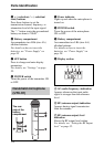
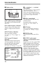
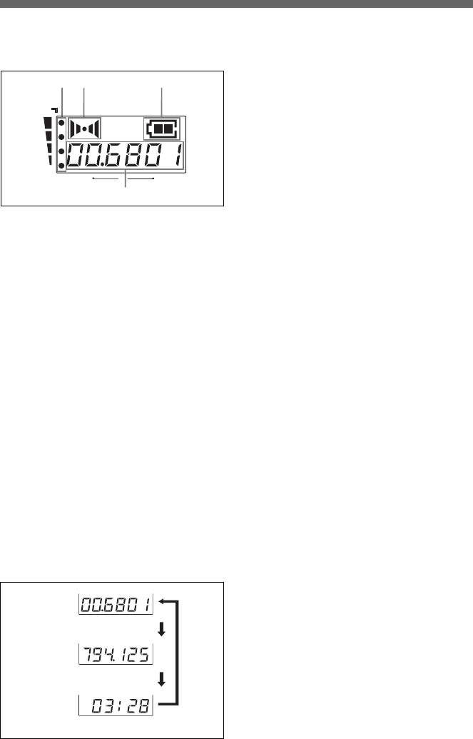
4 Display section
A RF (radio frequency) indications
The number of dots indicates the RF
input level.
B AF (audio frequency) indication
Appears whenever the output audio
signal is stronger than the reference
level.
C BATT (battery) indication
Shows the battery condition.
For details, see “Power Supply” on
page 20.
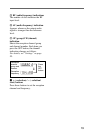
D GP (group)/CH (channel)
indication
Shows the reception channel group
and channel number. Each time you
press the SET button, the channel
indication changes as follows.
For details, see “Settings” on page 28.
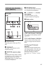
5 + (+ selection) / – (– selection/
reset) buttons
Press these buttons to set the reception
channel and frequency. The “–”
button resets the accumulated battery
use time to “00:00”. These buttons can
also be used to adjust the monitor
level.
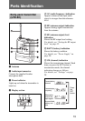
6 Battery compartment
Accommodates two LR6 (size AA)
alkaline batteries.
For details on how to insert the
batteries, see “Power Supply” on
page 20.
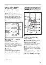
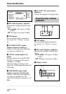
7 SET button
Press to change display parameters.
For details, see “Settings” on page
28.
8 POWER switch
Turns the power of the tuner ON or
OFF.
9 OUTPUT (audio output)
connector (3.5-mm diameter stereo
mini jack)
Connect one end of the supplied XLR-
BMP conversion cable or the stereo
mini plug-BMP conversion cable here
and the other end to the microphone
input on a camcorder, mixer, or
amplifier. If the microphone input
connector on the device connected to
the tuner is a stereo mini jack, connect
the straight (BMP) plug (2-pole) to the
tuner and the L-shaped (stereo mini)
plug (3-pole) to the microphone input
connector on the device.
AF
RF
BATT
CH
A
B
D
C
Reception
channel
group and
number
Reception
frequency
Accumulated
battery use
time
Press
the
SET
button.