


32
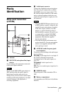
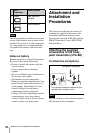
Parts Identification
Do not connect headphones with a
monaural mini jack. This may lead to short-
circuiting of the headphone output,
resulting in distorted sound output.
c RF (radio frequency) indicator
The color indicates the strength of the RF
input signal.
On (green): RF input is 15 dBµ
1)
or more.
Off: RF input is less than 15 dBµ
1)
.
1) 0 dBµ = 1 µVEMF
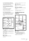
d POWER switch
Turns the power of the tuner ON or OFF.
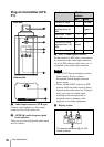
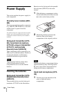
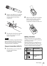
e Battery compartment
Accommodates two LR6 (size AA) alkaline
batteries.
For details on how to insert the batteries, see
“Power Supply” on page 34.
f + (+ selection) / – (– selection/reset)
buttons
Press these buttons to set the transmission
channel, frequency, or attenuation level of
the input signal.
The “–” button resets the accumulated use
time to “00:00”.
g SET button
Press to change and enter display
parameters.
For details, see “Tuner Settings” on page 42.
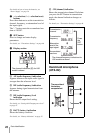
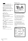
h Display section
A RF (radio frequency) indications
The number of dots indicates the RF input
level.
B AF (audio frequency) indication
Appears whenever the output audio signal
is stronger than the reference level.
C BATT (battery) indication
Shows the battery condition.
For details, see “Battery indication” on page 35.
D CH (channel) indication
Shows the reception channel group and
channel number. Each time you press the
SET button, the channel indication changes
as follows.
For details, see“Tuner Settings” on page 42.
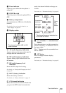
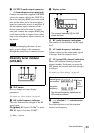
Note
The channel indication (C) for U30
model is shown.
Reception
channel group
and number
Reception
frequency
The channel/frequency indications for
U30 model are shown.
Press
the
SET
button.
Accumulated
use time