Page 12
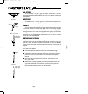
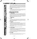
When the PFL switch is released the LED on the channel serves as a PEAK indicator,
to warn when an excessively high signal level is present in the channel. The signal is
sampled at three points in the channel, immediately after the Hi-Pass Filter (PRE-
INSERT), PRE-EQ and POST-EQ. The Peak LED will illuminate approximately 4dB
before clipping and therefore give warning of a possible overload even if the peaks are
removed by external equipment plugged into the Insert.
9 FADER
This 100mm long-throw fader determines the proportion of the channel in the mix
and provides a clear visual indication of channel level. Normal operating position is at the
`0 mark, providing 10dB of gain above that point if required.
STEREO INPUTS/RETURNS
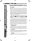
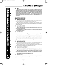
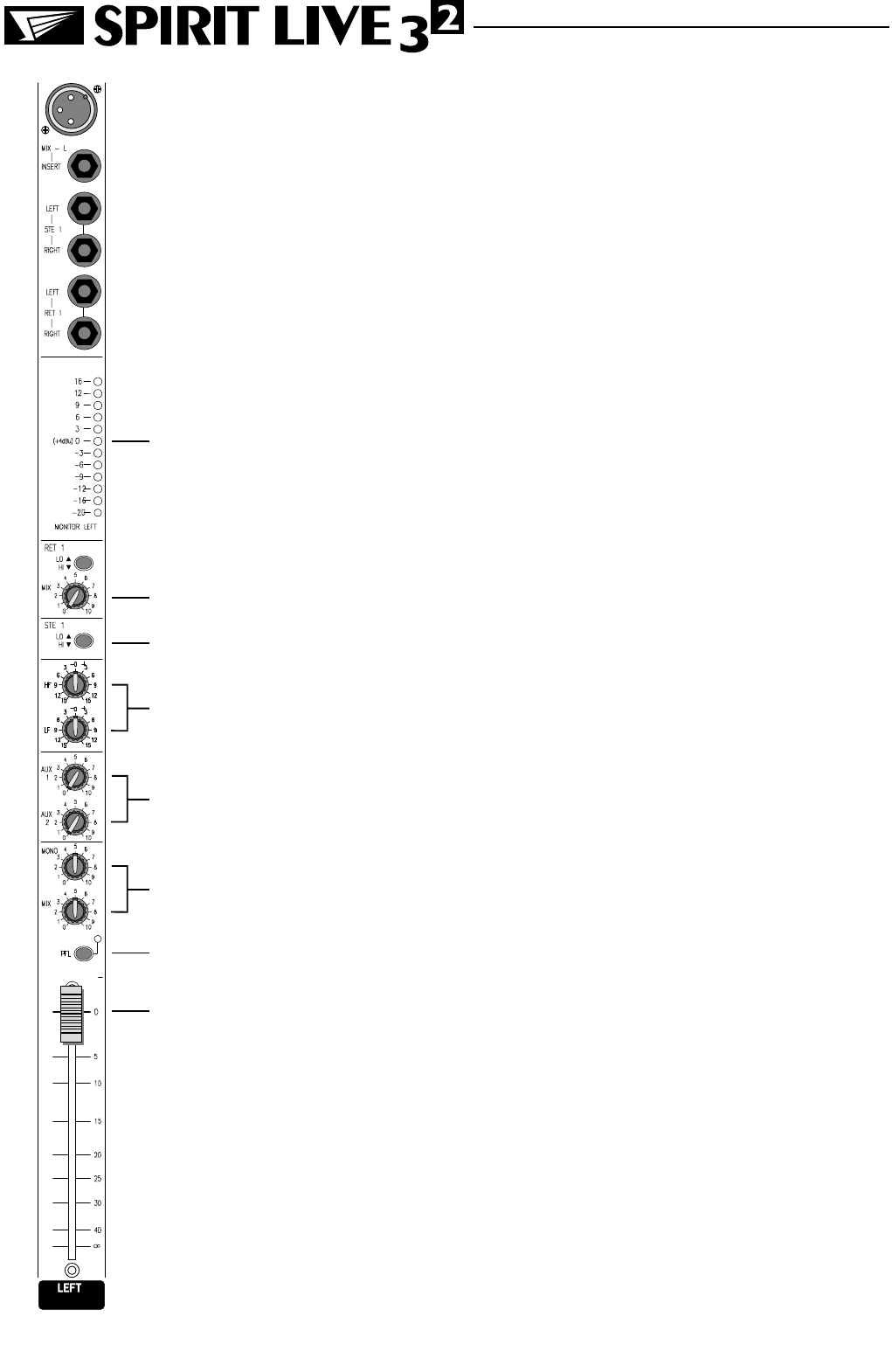
10 STEREO RETURNS
Two STEREO RETURNS are provided to allow external equipment to be returned to
the mixer and routed to the stereo Mix without using up valuable input channels. These
are an ideal way of mixing in the output of a reverb or effects unit, additional keyboards
or the output of other consoles used as sub-mixers. A mono return signal may be
plugged into the Left socket only of each pair to be fed equally to Left and Right busses.
The knobs should turned fully anticlockwise when not required.
STEREO INPUTS
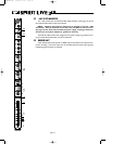
11 LO/HI
The LO/HI switch provides two input sensitivities. The LO setting (switch released)
should be selected for +4dBu professional equipment, and the HI setting (switch
pressed) should be selected for -10dBV semi-professional equipment. Start with the LO
setting if the source level is unknown.
12 EQUALISER
The Equaliser section has HF and LF shelving controls.
Turn the HF knob to the right to boost high (treble) frequencies by up to 15dB,
adding crispness to percussion from drum machines, synths and electronic instruments.
Turn to the left to cut these frequencies, reducing hiss or excessive brilliance.
Turn the LF knob to the right to boost low (bass) frequencies by up to 15dB, adding
extra punch to synths, guitars and drums. Turn to the left to reduce hum, boominess or
improve a mushy sound.
Set both knobs in the centre-detented position when not required.
13 AUXILIARY SENDS
These controls route a mono sum of the input channel signal to Auxiliary busses 1 &
2. These are separate from the main outputs and can therefore provide additional out-
puts for foldback, echo units or extra loudspeaker `fills.
The sends are always derived before the MIX or MONO controls and are not affect-
ed by the position of those controls or the Master section AUX 2 PRE switch. This
makes them particularly suitable for foldback or monitor feeds, which need to be con-
trolled separately from the main P.A. mix.
14 MIX, MONO
These controls set the level of the signal in stereo to MIX or as a mono sum to
MONO. The knobs should be turned fully anticlockwise when not required.
10
11
16
12
13
14
15
17
USERMAN.QXD 13/06/97 12:27 Page 12


