


10
Spectralizer
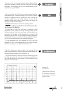
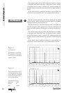
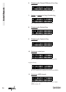
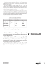
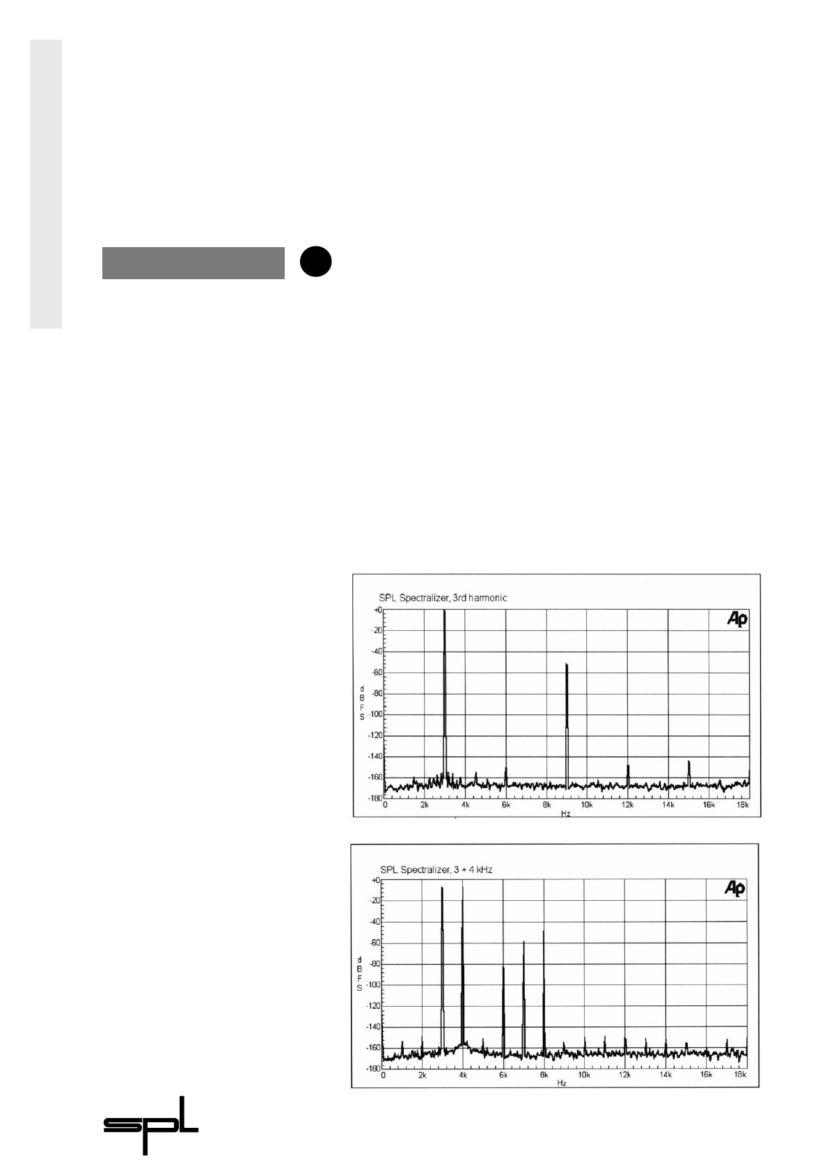
Diagram 3:
3
RD HARMONIC
The illustration shows the
FFT spectrums of the odd
harmonics for a measuring
signal of 3kHz.
Diagram 4:
If two frequencies are fed
into the Spectralizer (here
3 and 4kHz) also the diffe-
rential tone (here 7kHz)
are being produced
All measurements at:
F
REQUENCY 1kHz
D
ENSITY 0
M
IX 100%
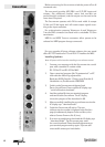
The control range is 0% to 100%. The 2ND HARMONIC encoder
is equipped with alpha-dial logic. Turning the encoder rapidly
causes the values to jump in steps of 10, whereas turning the
encoder slowly causes the values to proceed in single increment
steps.
If the need arises to make the harmonics more audible use
the D
ENSITY control (see DENSITY, 7) to increase their loudness.
The 3
RD HARMONIC encoder controls the intensity of the added
third harmonics which are being generated above the adjusted
highpass frequency (see F
REQUENCY, 3).
The third harmonics are odd harmonics which carry brilliance
but also sharpness and aggressiveness. A good combination of
even and odd harmonics is the key to a natural sounding top-
end.
The control range is 0% to 100%. The 3
RD HARMONIC encoder
is equipped with alpha-dial logic. Turning the encoder rapidly
causes the values to jump in steps of 10, whereas turning the
encoder slowly causes the values to proceed in single increment
steps.
If the need arises to make the harmonics more audible use
the D
ENSITY control (see DENSITY, 7) to increase their loudness.
Control Elements
3rd Harmonic
6